BVL V-MIX Fix Plus Assembly And Operating Manual Download Page 65

Cleaning

, maintenance and repairs


V-Mix Fix

 Plus 

Translation of the original assembly and operating manual 

65 


7.9.1 

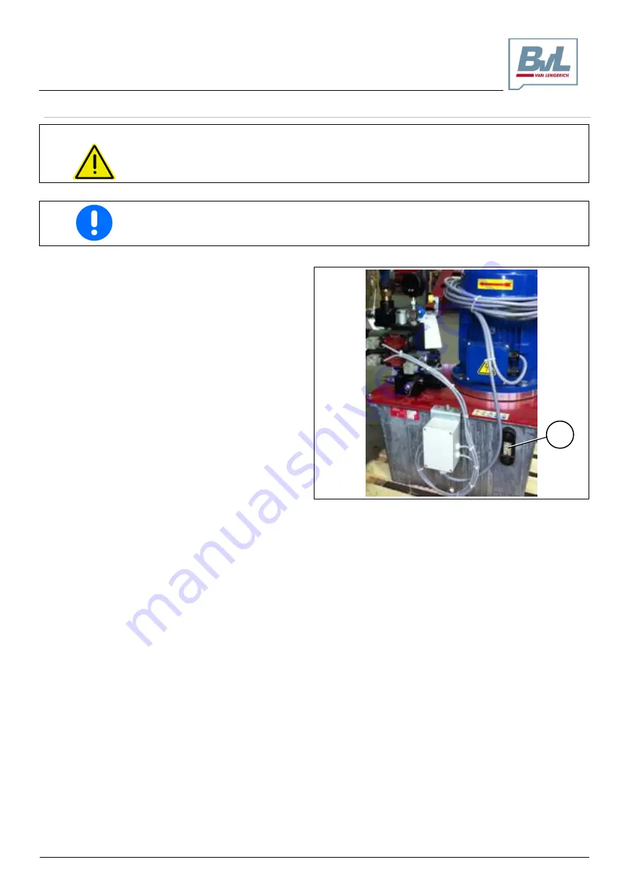
Checking the hydraulic oil level 

WARNING 


If oil is spilled during an oil change / oil refill, the resulting slip hazards can cause 
personal injury! 

Clean up spilled oil immediately with a binding agent. 


Check the hydraulic oil level daily before starting your work day. 


1. 

Read the hydraulic oil level at the oil sight glass 
(1).  

2. 

Top off hydraulic oil if the oil level is below the 
min. mark. Observe chapter "Refilling hydraulic 
oil"
, page 66 in this regard. 


Fig. 7-10 Hydraulic unit (sample photo) 


Summary of Contents for V-MIX Fix Plus

Page 1: ...lement2 Year of manufacture BA this manual PCS Item no 105625 DocuType Operating manual Assembly and Operating Manual V MIX FIX Plus Rev 2 08 17 Item no 106924 Printed in Germany Translation of the or...

Page 2: ...49 0 5903 951 0 Fax 49 0 5903 951 34 Internet http www bvl group de E mail info bvl group de Spare part orders Service For the address see the manufacturer s address Tel 49 0 5903 951 48 Fax 49 0 5903...

Page 3: ...operating the machine have read this assembly and operating manual be fore putting the machine into operation Special equipment is available for all machines When customizing your machine you may find...

Page 4: ...5 2 4 1 General information on safety and accident prevention 15 2 4 2 Use of the machine 15 2 4 3 Hydraulic system 16 2 4 4 Electrical system 16 2 4 5 Cleaning maintenance and repairs 17 2 5 Action r...

Page 5: ...order during filling 48 6 3 Discharging fodder 48 6 3 1 Removing clogs 50 7 Cleaning maintenance and repairs 51 7 1 Cleaning 52 7 2 Lubricating 52 7 2 1 The lubrication chart at a glance 52 7 2 2 Lub...

Page 6: ...tion 6 Translation of the original assembly and operating manual V Mix Fix Plus 8 Faults 71 9 Appendix 72 9 1 EC Declaration of Incorporation 72 9 2 Supplied third party manufacturer documentation 73...

Page 7: ...This operating manual describes how to operate clean service and repair the machine provides important information on how to handle the machine in a safe and efficient way If you have any questions pl...

Page 8: ...on for action 1 2 Instruction for action 2 Lists Unordered lists are displayed as lists with bullet points Example Item 1 Item 2 Item numbers in illustrations Figures included in round brackets refer...

Page 9: ...ructed according to the latest technological standards and the recognized safety and accident prevention regulations Regardless using the machine carries certain risks and may impair the life and limb...

Page 10: ...gloves o safety shoes o protective suit o skin protection etc 2 2 2 Responsibilities of the operator Before commencing work all personnel designated to work with on the machine are required to observe...

Page 11: ...l Activity Person specially trained to perform this activity 1 Instructed person 2 Person with professional training specialty work shop 3 Loading transport X X X Commissioning X X Setup adjustment X...

Page 12: ...m Intended use also comprises Use within the performance limits specified in the chapter 3 Technical data Use as intended and described in the operating manual Observing all information and regulation...

Page 13: ...f the manufacturer to do so Use only original spare parts or modification or accessory parts that have been approved by the manufacturer in order to ensure that the machine remains fully operational T...

Page 14: ...f the following causes Improper use of the machine Improper installation commissioning operation and maintenance of the machine Operating the machine with defective safety devices or improperly mounte...

Page 15: ...putting it into operation 2 4 2 Use of the machine Before starting to work familiarize yourself with all devices and controls of the machine and the way they operate It will be too late to do so when...

Page 16: ...draulic hose lines for more than six years including any storage time which must not exceed a period of two years Even if stored properly and only subjected to the permissible stress hoses and hose co...

Page 17: ...y attach and secure larger components using lifting devices before replacing them Regularly check nuts and bolt for tightness Re tighten loosened nuts and bolts Secure the raised machine raised parts...

Page 18: ...y symbol and a preceding signal word The signal word indicates the severity of the imminent danger DANGER DANGER indicates a situation of imminent danger that unless avoided carries a high risk of cau...

Page 19: ...ficient way possible is marked by the adjacent symbols IMPORTANT indicates an obligation to behave or act in a particular way in order to handle the machine in the proper manner Failure to observe thi...

Page 20: ...hazard The pictogram is composed of an image illustrat ing the hazard and enclosed by a triangular safety symbol 2 pictogram intended to help avoid the haz ard The pictogram is composed of an image p...

Page 21: ...ger area of the ma chine before you set the parts of the machine in motion Warning 72732 Risk of hands and fingers becoming cut or severed from the movements of parts that are accessible and moving wh...

Page 22: ...Warning 72740 Crushing hazard for fingers or hands caused by accessi ble moving parts of the machine These hazards may cause serious injury including death Secure the machine against starting up and...

Page 23: ...ctogram 1 Pictogram contains information regarding the proper handling of the machine The pictogram contain information in an image or descriptive text or in a table Order number and explanation 85203...

Page 24: ...ing pressure of the hydraulic system is 150 bar Instruction This pictogram provides instructions on how to activate the ventilation of the gear motor The transportation safety device needs to be remov...

Page 25: ...Plus Translation of the original assembly and operating manual 25 2 6 3 Positioning of warnings and instructions The following illustrations show the arrangement of warnings and instructions on the V...

Page 26: ...rnings may result in personal injury as well as danger to the environment and the machine including o Danger to human life due to unprotected work areas o Failure of important machine functions o Fail...

Page 27: ...Minimum height 600 mm support frame mm 2420 2380 2720 2400 2770 2770 2880 Unladen weight kg 2900 3650 3450 3750 4050 4150 4400 3 2 V MIX Fix Plus 13 2S to 24 2S Type 13 2S 15 2S 15N 2S 17 2S 17N 2S 2...

Page 28: ...d may not be altered or disfigured beyond recognition 1 Type plate 2 Machine number stamped into the frame Fig 3 1 Specified on the type plate are Manufacturer Type Machine no Year of manufacture Fig...

Page 29: ...N 51512 Hydraulic oil ISO VG 46 HLP DIN 51524 T2 Lubricating grease Multi purpose grease Lithium saponified grease NLGI 2 DIN 51502 BVL Farmgrease NSF H1 ISO 21469 3 7 Information on noise generation...

Page 30: ...at the machine This is the best way to become familiar with the machine 4 1 V MIX Fix at a glance The stationary mixer V Mix Fix Plus is designed exclusively for collecting reducing homogeneously mix...

Page 31: ...n window 9 Anti spill ring 11 Conveyor belt optional 2 Mixing and dispenser unit 4 Discharge area 6 Weighing system optional 8 Ladder 10 Hydraulic hand pump optional not shown in the image 4 3 Mixing...

Page 32: ...e gear motor 1 drives the gear unit 2 The rotation al movement of the dosing auger 3 is in turn initiated by the gear unit 2 The mixing auger 3 reduces mixes and transports the silage to the discharge...

Page 33: ...cutting blades enable adaption of the mixing system to the individual operating conditions and the structure of the components to be mixed Aggressive short mixing time higher power re quirement Degres...

Page 34: ...truc tured fodder over the edge of the container during the mixing process The anti spill ring is available in two models as a welded anti spill ring 1 standard equip ment as a flexible Vario ring 2 s...

Page 35: ...pper The counter blades are used for instance for the reduction and mixing of round or square bales can be swung into different positions inside the mixing hopper work with greater efficiency the fart...

Page 36: ...sing gate 1 is opened and closed by the hydraulic cylinder Fig 4 14 The opening width of the dosing gate 1 defines the quantity of the discharged fodder The set opening width of the dosing gate is ind...

Page 37: ...The inspection window 2 allows the operator to look into the mixing hopper and monitor the mixing process Fig 4 16 4 9 Conveyor belt optional Special equipment The V MIX Fix Plus is available with an...

Page 38: ...with the capability of storing multiple recipes including USB stick and PC interface Also observe the supplied operating manual of the weighing equipment Fig 4 18 Machines equipped with a cleaning mod...

Page 39: ...3 4 Optional for controlling an additional dosing gate or conveyor belt 5 Bypass valve Fig 4 20 4 12 Hydraulic hand pump optional Special equipment Instead of with a hydraulic unit the machine can als...

Page 40: ...g parts of the machine are unprotected during operation Do not put the machine into operation unless the safety equipment is completely in stalled and fully operational Replace defective safety equipm...

Page 41: ...on of the original assembly and operating manual 41 4 13 3 Motor and main drive shaft protective plates Protective plates 1 which prevent accidental reaching in are provided on the drive motor and in...

Page 42: ...additional information provided in the following chapters o Responsibilities of the operator on page 10 o Qualification of the personnel on page 11 o General safety instructions starting on page 15 o...

Page 43: ...e and secure it The ground bearing capacity at the installation location must be sufficient to ac commodate the machine weight for weight specifications refer to chapter Technical data starting on pag...

Page 44: ...ation 2 Align the machine such that the container is level 2 1 Loosen the clamping screws 1 at the feet of the machine 2 1 Adjust the height level of the machine using the height adjusting screws 2 2...

Page 45: ...s can be found on the cover of the gear motor They are also indicated in the operating manual of the motor manufacturer For an overview of supplied third party documents refer to chapter 9 Appendix 5...

Page 46: ...mpletely in stalled and fully operational The opening of guards while the machine is in operation is prohibited Close all guards which have been opened before operating the machine WARNING Risks of pe...

Page 47: ...en the mixing augers are under power The machine may overload if components become caught at the discharge opening and form clogs Overload has a negative impact on the performance and service life of...

Page 48: ...silage to the mixing hopper 6 Add feed components with a high water content e g brewer s grains potato pulp or sugar beet pulp 7 Add liquid components such as liquid yeast or molasses through the fill...

Page 49: ...er area 3 Open the block ball valve 1 Position vertical open Position horizontal closed 4 Switch the conveyor belt on see operating man ual of the overall plant 5 Open the dosing gate 2 see operating...

Page 50: ...cinity of raised parts Secure the machine against inadvertent start up before removing any clogging secure the main switch with a padlock Wait until the machine has come to a complete stop before ente...

Page 51: ...the machine is started inadvertently Secure the machine against inadvertent start up secure the main switch with a pad lock before working on the machine Wait until the machine has come to a complete...

Page 52: ...rt Remove all dirt from the lubrication nipples Use environmentally safe and biodegradable oils and greases if lubricants might en ter feedstuffs or the soil Contact your authorized farm equipment dea...

Page 53: ...Cleaning maintenance and repairs V Mix Fix Plus Translation of the original assembly and operating manual 53 7 2 2 Lubrication points overview Fig 7 1 250 h 50h rs 100 h 250 h...

Page 54: ...machine General visual inspection and function check daily Gear motor Visual inspection daily Gear unit Check oil level daily Change gear oil for the first time after 100 h then every 1000 h Dosing a...

Page 55: ...ating hours thereafter at least once per year whichever interval comes first Dispose of the used oil as stipulated by law If you experience problems with disposal contact your oil supplier If possible...

Page 56: ...rain plug 6 Screw in the oil drain plug 2 and firmly tighten it use a suitable sealant 7 Unscrew the plug 3 at the bottom end of the overflow pipe 5 8 Remove the oil hose 4 from the oil tank 9 Connect...

Page 57: ...drain plug 6 Screw in the oil drain plug 2 and firmly tighten it use a suitable sealant 7 Unscrew the plug 3 at the bottom end of the overflow pipe 5 8 Remove the oil hose 4 from the oil tank 9 Conne...

Page 58: ...Switch off the motor and secure against inadvertent restarting Refer to the operating manual of the overall plant for this purpose 2 Eliminate the cause of the overload e g foreign objects 3 Open the...

Page 59: ...t the block ball valve is closed Secure the machine against inadvertent start up before climbing into the dispenser container secure the main switch with a padlock WARNING Risks of personal injury fro...

Page 60: ...en the bolt joint 2 between cover apron 3 and mixing hopper 4 6 Slightly raise the cover apron to pull the flat iron of the cover apron out of the bracket 5 You can now swing the apron slightly to the...

Page 61: ...on This is necessary to for instance keep the discharge arm or the beginning of the auger from converging simultaneously during mixing thus generating excessive torque Such excessive torque may for ex...

Page 62: ...se severe injury in particular eye injuries Always wear safety goggles while sharpening cutting blades Use an angle grinder with a flapped disc Fig 7 8 to sharpen the cutting blades Carefully resharpe...

Page 63: ...ge guard to cover the cutting blades during assembly work on the cutting blades 1 Enter the empty mixing hopper to replace the cut ting blades via a discharge opening Also observe the chapter Entering...

Page 64: ...n expert verify the proper technical condition of the hydraulic hose lines at least once per year Replace hydraulic hose lines when detecting damage and wear Use only original hydraulic hose lines sup...

Page 65: ...efill the resulting slip hazards can cause personal injury Clean up spilled oil immediately with a binding agent Check the hydraulic oil level daily before starting your work day 1 Read the hydraulic...

Page 66: ...uids with organic hydraulic fluids 1 Secure the machine against inadvertent start up 2 Remove the lid 1 3 Fill the hydraulic oil tank with suitable fresh hy draulic oil 3 1 Make sure the hydraulic oil...

Page 67: ...insert e g from chafing cuts cracks Embrittlement of the outer layer evident through the formation of the cracks in the hose material Unnatural deformation of the hydraulic hose line e g layer separa...

Page 68: ...e lines Prevent hydraulic hose lines from rubbing against components or against one another by arranging and fastening them properly Protect hydraulic hose lines with protective sleeves if necessary C...

Page 69: ...he conveyor belt at least every 25 operating hours 7 10 1 Belt connection Check the conveyor belt and the belt connection 1 of the conveyor belt for obvious defects on a weekly ba sis Replace the conv...

Page 70: ...8 13 25 35 41 M 8x1 27 38 41 M 10 16 17 49 69 83 M 10x1 52 73 88 M 12 18 19 86 120 145 M 12x1 5 90 125 150 M 14 22 135 190 230 M 14x1 5 150 210 250 M 16 24 210 300 355 M 16x1 5 225 315 380 M 18 27 290...

Page 71: ...lete stop before entering the danger area Fault Cause Remedy The mixing auger does not turn when the drive shaft is activated A shear bolt on the shear bolt cou pling upstream from the planetary gear...

Page 72: ...rective 2006 42 EC have been applied and observed Annex I Articles 1 1 2 1 1 3 1 1 5 1 3 1 1 3 2 1 3 4 1 3 7 1 3 8 1 3 8 2 1 3 9 1 4 1 1 4 2 1 1 5 1 1 5 15 1 5 4 1 5 8 1 6 4 1 7 1 1 7 2 1 7 3 1 7 4 1...

Page 73: ...embly and operating manual 73 9 2 Supplied third party manufacturer documentation Manufacturer Designation Getriebebau Nord GmbH Co KG Gear motor operating manual PTM Weighing unit operating manual Wa...

Page 74: ...eaning maintenance and repairs 17 Electrical system 16 Hydraulic system 16 Use of the machine 15 H Hazard meaning 8 Hydraulic hand pump 39 Hydraulic system 38 I Information on safety and accident prev...

Reviews: