5
Installation
Logano plus SB325 – 6 720 806 328 (2013/07)
23
5.9.4
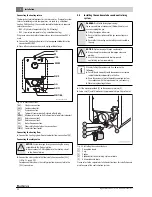
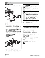
Fitting the back plate
▶ Secure the lower boiler cover [1] with 5 self-tapping screws [2] to the
side panels.
▶ Insert the upper rear panel section [4] with the Z-fold behind the
lower rear panel section, and secure onto the side panels with four
self-tapping screws [3].
▶ Make sure that the two upper self-tapping screws also pass through
the connection plates.
▶ Secure one or two cable clips [5] or a cable conduit on the fold on the
upper back panel.
Fig. 23 Screwing the 2-part back panel in place (boiler rating 145 to
310 kW)
[1]
Lower back panel
[2]
5 self-tapping screws
[3]
4 self-tapping screws
[4]
Upper back panel
[5]
Cable clamp/cable channel
5.9.5
Fitting the boiler cover
Fitting the boiler cover sections
Fitting the boiler front cover
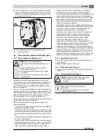
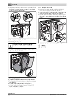
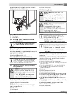
▶ Place front boiler cover [1] on top of the angled edges of the side
panels and pull forwards until the right and left-hand hooks click into
place in the slot (
Fig. 24).
▶ Screw front boiler cover [1] firmly into the side tie bars by screwing 2
self-tapping screws through the tabs on the boiler cover and the
angled edge on the side panels.
▶ After installing the cables and temperature sensors, position the rear
boiler cover section on the right and left-hand side panels and screw
into place.
Fig. 24 Fitting the front boiler cover.
5.9.6
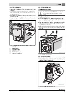
Fitting the front panel
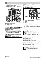
▶ Push the tabs on the lower tie-bar from below into the slots to the left
and right on the side panels and secure the tie-bar with two machine
screws on the front of the boiler shell.
Fig. 25 Securing the lower connection plate
6 720 804 354-10.1ITL
2
1
3
5
5
4
The first cover section is provided with a recess. The rear
parts are identical and are positioned with their fold
forward.


