5
Installation
Logano plus SB325 – 6 720 806 328 (2013/07)
19
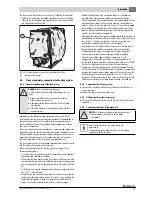
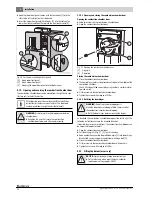
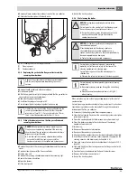
▶ Place the rear thermal insulation section [1] onto the back panel of
the boiler in the position dictated by the recesses and secure to the
right and the left onto the wrap-around thermal insulation mat with
two spring hooks on each side.
Fig. 14 Positioning and securing the rear insulation section
[1]
Rear panel insulation
5.4
Flue gas and water connections for heating system
5.4.1
General requirements of the flue system
Implementing the following recommendations concerning to the
installation of flue systems should guarantee trouble-free operation of
the combustion system. Failure to observe these requirements can
result in substantial operating problems during combustion and may
even result in explosions.
These are frequently acoustic disturbances, compromised combustion
stability or excessive vibrations on assemblies or their components. Low
NOx combustion systems are to be viewed as being more sensitive to
operating faults on account of their combustion control. Therefore,
engineer and implement the flue system with particular care.
The flue system consists of a connection piece between the heat source
and the vertical flue system itself (chimney).
When sizing and implementing the flue system, comply with the
following requirements:
• Size flue systems in accordance with the respective national and local
regulations and applicable standards.
• When selecting the material for the flue system, take into account the
composition and temperatures of the flue gas to prevent damage and
contamination of the system components that are in contact with flue
gas.
• Only flue systems, which are approved for a flue gas temperature of at
least 120 °C, may be used.
• Route the flue gas as directly as possible to the chimney considering
the best possible flow characteristics (e.g. short, rising, and with the
fewest possible bends). Provide a separate vertical flue for each
boiler. Take the thermal expansion of the system into account.
• Implement deviations in the connection pieces as favourably as
possible where flow is concerned by using bends or deflectors.
Connection pieces with several deviations should be avoided, as they
would have a detrimental effect on air-borne and structure-borne
noise as well as the start-up pressure hammer. Prevent sharp-edged
joints between rectangular connection flanges and the connection
pipe. As with any reductions/expansions that may be required, the
angle of the joint should not exceed 30°.
• Where possible, connection pieces should be joined to the chimney to
provide optimum flow characteristics and with an incline (at an angle
less than 45°). Any terminal pieces at the chimney outlets must
ensure the free discharge of flue gas into atmosphere.
• Any condensate must be able to drain freely over the entire length,
be treated and drained off in accordance with local regulations.
• Provide inspection pieces in accordance with local regulations,
if necessary after discussion with the local authorising body.
• The chimney must be separated from the boiler (e.g. with
compensators) to prevent the transfer of structure-borne noise.
• If a flue gas damper is installed in the flue system, integrate an "OPEN"
limit switch into the boiler control system for safety reasons.
Combustion must only be able to start when the feedback from the
limit switch confirms that the flue damper is fully open. A temperature
drop inside the boiler is possible on account of the time it takes the
actuator to move the damper into position. Set the "CLOSE" limit
position at the flue gas damper in such a way that it never closes fully.
This prevents damage to the fitted burner through heat build up.
5.4.2
Connecting the flue gas system
▶ Connect the connecting piece onto the flue outlet and the flue gas
system (chimney).
▶ Support the connecting piece if necessary.
5.4.3
Fitting a sealing collar (accessory)
▶ Fit the sealing collar in accordance with the installation instructions
supplied.
5.4.4
Connecting the boiler to the pipework
DANGER:
Risk to life through poisoning!
Insufficient ventilation can lead to dangerous flue gas
leaks!
▶ Never close off or reduce the size of ventilation,
supply and extract air vents.
▶ Never operate the boiler unless faults are rectified
immediately.
▶ Inform the operator in writing of any faults and their
associated risks.
NOTICE:
System damage due to leaking connections!
▶ Connect pipes without stress to the boiler
connections.
Boiler contamination on the water side is not
permissible.
If required to prevent contamination, install a sludge
separator in the boiler return.


