5
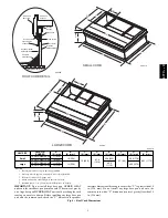
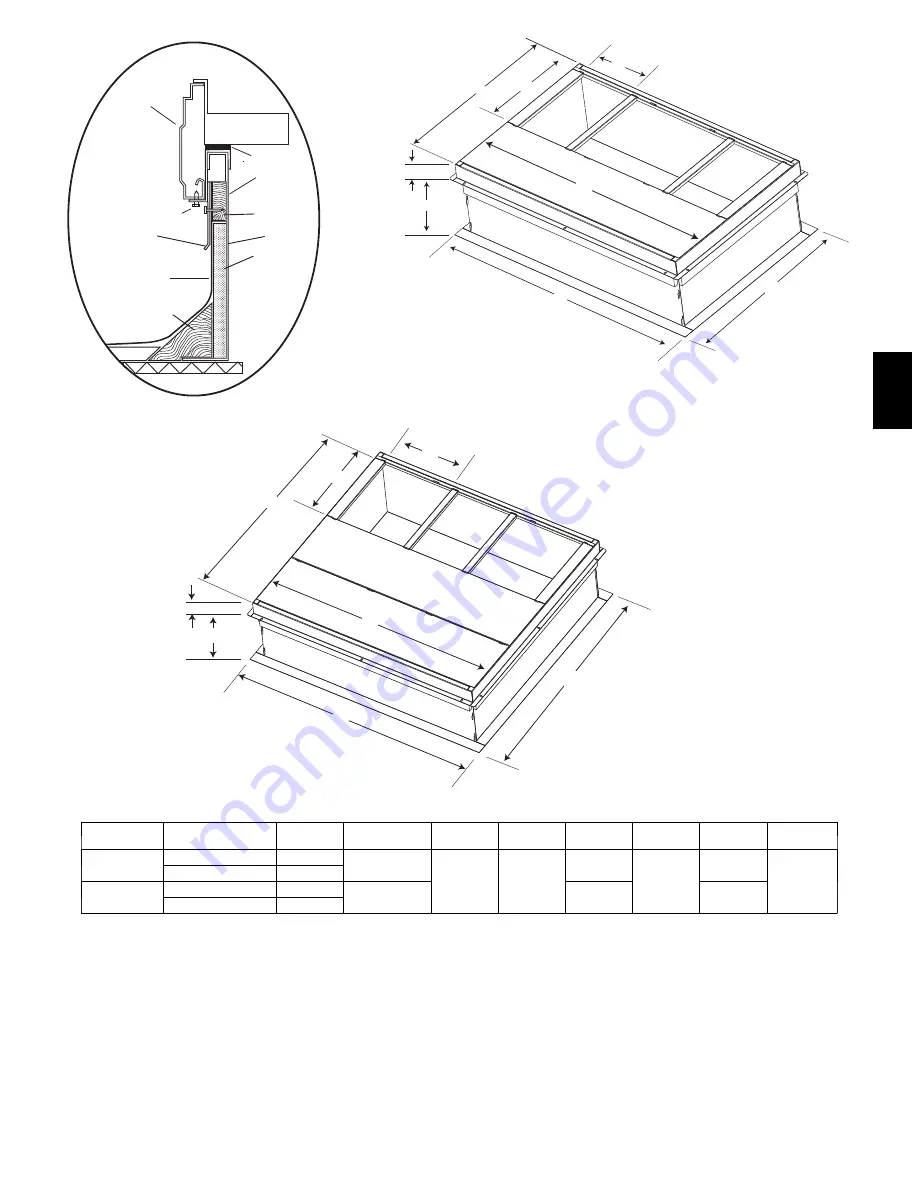
LARGE CURB
SMALL CURB
ROOF CURB DETAIL
Wood nailer*
Roofcurb*
Insulation
(field supplied)
*Provided with roofcurb
Cant strip
field supplied
Roofing material
field supplied
Flashing field
supplied
HVAC unit
base rails
Roofcurb
Sealing
Gasket
HVAC unit
basepan
Anchor screw
A09090
A09415
A09418
C
B
A
F
D
E
G
H
C
B
A
D
E
H
F
G
A09419
UNIT SIZE
CATALOG
NUMBER
A
IN. (mm)
B
IN. (mm)*
C
IN. (mm)
D
IN. (mm)
E
IN. (mm)
F
IN. (mm)
G
IN. (mm)
H
IN. (mm)
Small
CPRFCURB010A00
11 (279)
10 (254)
16 (406)
47.8
(1214)
32.4 (822)
2.7 (69)
30.6 (778)
46.1 (1170)
CPRFCURB011A00
14 (356)
Large
CPRFCURB012A00
11 (279)
14 (356)
43.9
(1116)
42.2 (1072)
CPRFCURB013A00
14 (356)
NOTES:
1. Roof curb must be set up for unit being installed.
2. Seal strip must be applied, as required, to unit being installed.
3. Roof curb is made of 16--gauge steel.
4. Attach ductwork to curb (flanges of duct rest on curb).
5. Insulated panels: 1--in. (25.4 mm) thick fiberglass 1 lb. density.
IMPORTANT
: Do not install large base pan HYBRID HEAT
units onto the small base pan (common curb). The center of gravity
on a large base pan HYBRID HEAT unit could overhang the curb
causing an unsafe condition. Before installing any large base pan
unit onto the common curb, check the “Y” distance in the product
literature dimensional drawing to ensure that “Y” is greater than 14
in. (356 mm). Do not install any large base pan unit onto the
common curb with a “Y” dimension (center of gravity) less than 14
in. (356 mm).
Fig. 4 -- Roof Curb Dimensions
677C
--
--
C
Summary of Contents for Legacy 677C**C Series
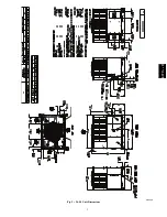
Page 3: ...3 A150538 Fig 2 24 30 Unit Dimensions 677C C...
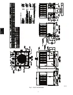
Page 4: ...4 A150539 Fig 3 36 60 Unit Dimensions 677C C...
Page 44: ...44 A150506 Fig 15 208 230 1 60 Connection Wiring Diagram 677C C...
Page 45: ...45 A150516 Fig 15 Cont 208 230 1 60 Ladder Wiring Diagram 677C C...
Page 46: ...46 A150507 Fig 16 208 230 3 60 Connection Wiring Diagram 677C C...
Page 47: ...47 A150517 Fig 16 Cont 208 230 3 60 Ladder Wiring Diagram 677C C...


