57
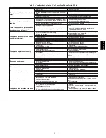
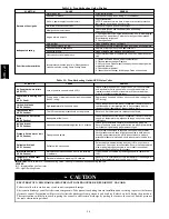
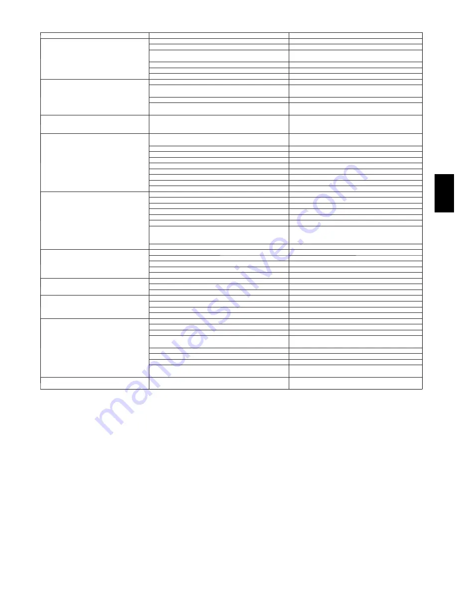
Table 13 – Troubleshooting Guide -- Cooling or Heat Pump Heating Mode
SYMPTOM
CAUSE
REMEDY
Compressor and Outdoor fan will not
start.
Power Failure
Call power company.
Fuse blown or circuit breaker tripped
Replace fuse or reset circuit breaker.
Defective thermostat, contactor, transformer, or control
relay
Replace component.
Insufficient line voltage
Determine cause and correct.
Incorrect or faulty wiring
Check wiring diagram and rewire correctly.
Thermostat setting too high
Lower thermostat setting below room temperature.
Compressor will not start but Outdoor
fan runs.
Faulty wiring or loose connections in compressor circuit
Check wiring and repair or replace.
Compressor motor burned out, seized, or internal over-
load open
Determine cause Replace compressor.
Defective run/start capacitor, overload, start relay
Determine cause and replace.
One leg of 3---phase power dead
Replace fuse or reset circuit breaker. Determine
cause.
Three---phase scroll compressor makes
excessive noise, and there may
be a low pressure differential.
Scroll compressor is rotating in the wrong direction
Correct the direction of rotation by reversing the
3---phase power leads to the unit.
Compressor cycles (other than normally
satisfying thermostat).
Refrigerant overcharge or undercharge
Recover refrigerant, evacuate system, and recharge
to capacities shown on nameplate.
Defective compressor
Replace and determine cause.
Insufficient line voltage
Determine cause and correct.
Blocked Outdoor
Determine cause and correct.
Defective run/start capacitor, overload or start relay
Determine cause and replace.
Defective thermostat
Replace thermostat.
Faulty Outdoor---fan motor or capacitor
Replace.
Damaged reversing valve
Determine cause and correct
Restriction in refrigerant system
Locate restriction and remove.
Compressor operates continuously.
Dirty air filter
Replace filter.
Unit undersized for load
Decrease load or increase unit size.
Thermostat set too low
Reset thermostat.
Low refrigerant charge
Locate leak, repair, and recharge.
Mechanical damage in compressor.
Replace compressor.
Air in system
Recover refrigerant, evacuate system, and recharge.
Frosted coil with incorrect defrost operation
Check defrost time settings, Reset as necessary
Check defrost temperature switch, Replace as nec-
essary
Outdoor coil dirty or restricted
Clean coil or remove restriction .
Excessive head pressure.
Dirty air filter
Replace filter.
Dirty Indoor or Outdoor coil
Clean coil.
Refrigerant overcharged
Recover excess refrigerant.
Air in system
Recover refrigerant, evacuate system, and recharge.
Indoor or Outdoor air restricted or air short---cycling
Determine cause and correct.
Head pressure too low.
Low refrigerant charge
Check for leaks, repair, and recharge.
Compressor IPR leaking
Replace compressor.
Restriction in liquid tube
Remove restriction.
Excessive suction pressure.
High heat load
Check for source and eliminate.
Compressor IPR leaking
Replace compressor.
Refrigerant overcharged
Recover excess refrigerant.
Reversing valve hung up or leaking internally
Replace valve
Suction pressure too low.
Dirty air filter
Replace Filter.
Low refrigerant charge
Check for leaks, repair, and recharge.
Metering device or low side restricted
Remove source of restriction.
Insufficient Indoor airflow
Increase air quantity. Check filter — replace if neces-
sary.
Temperature too low in conditioned area
Reset thermostat.
Outdoor ambient below 55
F (12.8
C)
Install low---ambient kit.
Field---installed filter---drier restricted
Replace.
(Heat) Outdoor coil frosted
Move timer on control board to 30 minutes between
defrost cycles
Compressor runs but outdoor fan does
not
NC (normally closed) contacts on defrost board open
Check condition of relay on board Replace if neces-
sary
677C
--
--
C
Summary of Contents for Legacy 677C**C Series
Page 3: ...3 A150538 Fig 2 24 30 Unit Dimensions 677C C...
Page 4: ...4 A150539 Fig 3 36 60 Unit Dimensions 677C C...
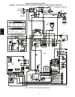
Page 44: ...44 A150506 Fig 15 208 230 1 60 Connection Wiring Diagram 677C C...
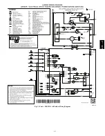
Page 45: ...45 A150516 Fig 15 Cont 208 230 1 60 Ladder Wiring Diagram 677C C...
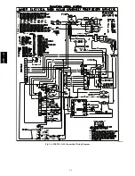
Page 46: ...46 A150507 Fig 16 208 230 3 60 Connection Wiring Diagram 677C C...
Page 47: ...47 A150517 Fig 16 Cont 208 230 3 60 Ladder Wiring Diagram 677C C...

