background image

SETUP = HEAT PUMP / AC:

COOLING LOCKOUT:

NONE (default)

45° F.

50° F.

55° F.

Outside temperature below which cooling will not be provided.

ENTERED SIZE:

(dependent on indoor unit model)

Size of the outdoor unit entered during the start-up process. If the
outdoor unit is a communicating model, this value will not be
shown. This size can be changed here but is limited to sizes that the
indoor unit can handle.

DEFROST INTERVAL:

30 minutes

60 minutes

90 minutes (default)

120 minutes

Time interval at which defrost cycles can occur on a heat pump.

ELECT HEAT LOCKOUT:

NONE (default)

+5 to 55 deg. F

Outside temperature above which the electric heat will not operate.

HIGH COOL LATCH:

NONE (default)

80 - 110 deg F

Outside temperature above which only the high speed (of a
2-speed outdoor unit) will run when cooling.

A.

Setup = ACCESSORIES

FILTER TYPE:

MEDIA

EAC

MEDIA+EAC

CLEAN INTERVAL: 30 to 180 days (of blower operation).
(Default = 90)

Interval at which the Clean Filter notification will turn on. Applies
to EAC or MEDIA+EAC filter selection only.

B.

Setup = Humidifier

HUMIDIFIER INSTALLED:

NO

YES

If YES, indicates to the system whether a humidifier is installed
and enables humidification functions.

CHANGE PAD INTERVAL: 1 to 24 months of humidifier
operation (default=6 months)

Interval at which the Change Humidify Pad notification will be
displayed.

HUMIDIFY WITH FAN:

NO (default)

YES

If YES, the humidifier will run with Continuous Fan if there is a
humidify demand.

SETUP = VENTILATOR

NOTE:

Only appears if ventilator is installed.

CLEAN INTERVAL:

60 to 180 days of operation (default=90)

Interval at which the Clean Ventilator Pre-filter notification will
turn on.

SETUP = UV LIGHTS

UV LIGHTS INSTALLED:

NO

YES

If YES, indicates to the system whether UV lights are installed.

CHANGE INTERVAL:

6 to 48 months operation time (default=12 months)

Interval at which the Change UV Lights notification will be
displayed.

SETUP = SYSTEM MAINTENANCE

REMIND OWNER OF ROUTINE MAINTENANCE EVERY:

This setup is used to adjust the timer interval in which the normal
System Maintenance notification is turned on for the homeowner.

Range= OFF, 6 to 24 months, (default=12)
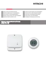
CHECKOUT MENUS

The Checkout menu will show the equipment installed in the
system. A sample checkout menu is shown in Fig. 24.

Checkout = FURNACE

Make sure the furnace is properly installed before continuing.

LOW HEAT RUNTIME: 5 min.

HIGH HEAT RUNTIME: 5 min.

This menu item allows the furnace to be exercised. First, a low
heat runtime and high heat runtime are selected.

If only the low heat is to be exercised:

The furnace will execute its ignition start-up sequence. This
sequence will be displayed on the Evolution Control screen. After
the gas valve and blower motor turn on, the screen will automati-
cally change to show the current operating status of the furnace.

Checkout = FAN COIL

ELECTRIC HEAT CHECK

ELECTRIC HEAT RUNTIME: 5 min., Default time = 5 min.,
Range = 0 - 120 min.

If you have a fan coil with electric heaters, this menu item will
allow the heaters to be exercised.

With self-identifying electric heaters, three stages of electric heat
are available to be exercised in any combination. Non-identifying
heaters will only provide one stage of heat.

Enter the run time (in minutes) of each stage of heat to be
exercised then press START (right-side button). The display will
change to show the fan coil’s operating status.

Fig. 24 — CHECKOUT MENUS

A03204

CHECKOUT

FURNACE
HEAT PUMP HEATING
HEAT PUMP COOLING
HUMIDIFIER
VENTILATOR

   BACK               SELECT

—9—

Summary of Contents for Evolution Control SYSTXBBUID01

Page 1: ...rmo stat plus much more and a variable speed furnace or FE fan coil They support controlled ventilation humidification dehumidifica tion and air quality control Either a two speed communicating or a standard 24 vac controlled outdoor unit may be used When using conventional outdoor units the variable speed furnace or fan coil provides the 24 volt signals needed to control them Also the Evolution N...

Page 2: ...WG or larger NOTE ABCD bus wiring only requires a four wire connection however it is good practice to run thermostat cable having more than four wires in the event of a damaged or broken wire during the installation Each device in the Evolution System has a four pin connector labeled ABCD It is recommended that the following color code be used when wiring each device A Green Data A B Yellow Data B...

Page 3: ...volution Control mounting plastic recess mount or surface mount and decorative backplate if desired 4 Route wires through large hole in mounting plastic Level rear plastic against wall for aesthetic value only Evolution Control need not be level to operate properly and mark wall through two mounting holes 5 Drill two 3 16 inch mounting holes in wall where marked Fig 4 Surface Mount Backplate A0318...

Page 4: ...perature sensor may be installed not required at the indoor furnace or fan coil OAT terminals When OAT is applied the Evolution System will provide full system features and benefits See wiring diagram Fig 14 for a Typical Connection Diagram for FE fan coil with a 1 speed heat pump using non communicating outdoor unit When OAT is applied the Evolution System will provide full system features and be...

Page 5: ...None no unit installed Press the right side button to continue to the next screen If you have selected either AC or HP as the outdoor unit type the following middle screen will appear See figure 16 Press either Time or Temp buttons to select appropriate Btu size of outdoor unit then press right side button to continue If a NIM Network Interface Module is applied for non communicating two speed out...

Page 6: ...lso after selecting YES if the filter type is not an EAC the indoor unit will operate the blower for one minute to do a system static pressure check QUICK START For first time installers Quick Start will allow you to start up the Evolution System before you have the chance to learn all the details of system operation However for the best possible comfort and operation we recommend that you refer t...

Page 7: ...RVICE MENUS The INSTALL SERVICE menus contain a set of vital information This information enables the Installer or Service person to view a summary of what has been installed etc To enter INSTALL SERVICE menus press and hold the ADVANCED button for at least ten seconds The following menu will appear See figure 20 NOTE The INSTALL SERVICE menu will automatically exit after 60 minutes of no push but...

Page 8: ...ncreased comfort AC AIRFLOW COMFORT default EFFICIENCY MAXIMUM Selects the airflow of the furnace when cooling COMFORT is a decreased airflow used to improve humidity control EFFI CIENCY is the airflow used to meet specified ratings MAXI MUM is a fixed airflow speed of 400 CFM ton based on the outdoor unit size DEHUM AIRFLOW NORMAL default HIGH NORMAL airflow adjustment is used during dehumidifyin...

Page 9: ...turn on SETUP UV LIGHTS UV LIGHTS INSTALLED NO YES If YES indicates to the system whether UV lights are installed CHANGE INTERVAL 6 to 48 months operation time default 12 months Interval at which the Change UV Lights notification will be displayed SETUP SYSTEM MAINTENANCE REMIND OWNER OF ROUTINE MAINTENANCE EVERY This setup is used to adjust the timer interval in which the normal System Maintenanc...

Page 10: ...lockout timer is active this will show the current time value See furnace manual for details on lockout timers Service FAN COIL ELECTRIC HEAT STATUS OFF LOW MED HIGH Displays stages of electric heat that the fan coil is currently delivering AIRFLOW CFM fan coil model dependent Cubic Feet per Minute of air the blower is currently delivering BLOWER RPM Blower motor RPM value STATIC PRESS Inches of w...

Page 11: ...e equipment is not cycled more than the selected times per hour This timer is adjustable from 4 to 6 cycles per hour This timer is defeated for one cycle when the desired temperature is manually changed It can also be defeated for one cycle by simultaneously pressing the Fan and Temp buttons Ten Minute Staging Timer In multistage heating or cooling this timer prevents any higher stage from turning...

Page 12: ...l fuel Code 41 Blower Motor Fault USER INTERFACE No communication with indoor unit SYSTEM MALFUNCTION SCREEN The following errors will cause a System Malfunction Screen to pop up FAN COIL Code 37 Heater output sensed ON when not energized FURNACE Code 13 Limit Circuit Lockout Code 14 Ignition Lockout Code 21 Gas Heating Lockout Code 22 Abnormal Flame Proving Signal dual fuel only Code 23 Pressure ...

Reviews: