


the outdoor-fan motor will be energized. On units with econo-
mizer, the economizer damper blade will move to the mini-
mum position. The unit will now operate in the heating mode.
If the space thermostat is satisfied during a defrost cycle, the
unit will continue in the defrost mode until the time or tem-
perature constraints are satisfied.
II. COOLING SECTION START-UP AND ADJUSTMENTS
CAUTION:
Complete the required procedures given
in the Pre-Start-Up section on page 18 before starting
the unit.
Do not jumper any safety devices when operating the
unit.
Do not operate the compressor in cooling mode when
the outdoor temperature is below -4 C (25 F).
Do not rapid-cycle the compressor. Allow 5 minutes be-
tween ‘‘on’’ cycles to prevent compressor damage.
A. Checking Cooling Control Operation
Start and check the unit for proper cooling control operation
as follows:
1. Place room thermostat SYSTEM switch in OFF posi-
tion. Observe that blower motor starts when FAN switch
is placed in ON position and shuts down when FAN switch
is placed in AUTO. position.
2. Place SYSTEM switch in COOL position and FAN switch
in AUTO. position. Set cooling control below room tem-
perature. Observe that compressor, outdoor fan, and in-
door blower motors start. Observe that cooling cycle shuts
down when control setting is satisfied.
3. When using an auto.-changeover room thermostat, place
both SYSTEM and FAN switches in AUTO. positions.
Observe that unit operates in heating mode when tem-
perature control is set above room temperature and op-
erates in cooling mode when temperature control is set
below room temperature.
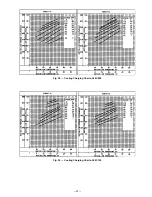
B. Checking and Adjusting Refrigerant Charge
The refrigerant system is fully charged with R-22 refriger-
ant, tested, and factory sealed.
NOTE:
Adjustment of the refrigerant charge is not required
unless the unit is suspected of not having the proper R-22
charge. This unit uses charging charts to determine proper
charge. See Refrigerant Charge section on page 26 for fur-
ther details.
C. Unit Controls
All compressors have the following internal-protection
controls:
1. High-Pressure Relief Valve — This valve (internal to the
compressor) opens when the pressure differential be-
tween the low and high side becomes excessive and will
reset automatically when pressure returns to normal.
2. Compressor Overload — This overload interrupts power
to the compressor when either the current or internal
temperature becomes excessive, and automatically re-
sets when the internal temperature drops to a safe level.
This overload may require up to 60 minutes (or longer)
to reset; therefore, if the internal overload is suspected
of being open, disconnect the electrical power to the unit
and check the circuit through the overload with an ohm-
meter or continuity tester.
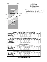
D. Cooling Sequence of Operation (See Fig. 31)
With Accessory Economizer
Upon a request for cooling from the space thermostat, termi-
nals Y1 and G will be energized with 24 v. As a result, the
indoor-fan contactor (IFC) and indoor-fan motor (IFM) will
be energized and the economizer damper blade will open to
minimum position. Note that if the indoor fan is on when the
space thermostat calls for cooling, terminal G is already
energized and the economizer damper blade is at minimum
position.
If the outdoor-air temperature is below the outdoor-air ther-
mostat (OAT) setting, then the position of the damper blade
will be determined by the temperature of the discharge air
as sensed by the discharge-air thermistor (DAT). The damper
blade will slide open for 5 seconds, and rest for 30 seconds
until the proper discharge-air temperature is obtained. The
damper blade will modulate to different positions to main-
tain this discharge-air temperature.
If the thermostat calls for a second stage of cooling by sup-
plying 24 v to Y2, the outdoor-fan contactor (OFC) and Com-
pressor contactor no. 1 (C1) will be energized, which will bring
on the outdoor fan and Compressor no. 1, respectively.
When the thermostat is satisfied, Y2 will be deenergized first,
which will deenergize the outdoor fan and Compressor no. 1.
When the indoor fan is deenergized, the economizer will re-
turn to a fully closed position.
If the outdoor-air temperature is above the OAT setting, the
economizer will move to the minimum position and the unit
will operate as described in Without Accessory Economizer
section below.
Without Accessory Economizer
Upon a request for cooling from the space thermostat, termi-
nals Y1 and G will be energized with 24 v. As a result, the
indoor-fan contactor (IFC), outdoor-fan contactor (OFC) and
Compressor contactor no. 1 (C1) will be energized, which in
turn will energize the indoor fan, outdoor fan and Compres-
sor no. 1, respectively.
If the space thermostat calls for a second stage of cooling by
supplying 24 v to Y2, Compressor contactor no. 2 (C2) will be
energized, thus energizing Compressor no. 2.
When the space thermostat is satisfied, Y2 will be deener-
gized first, which will deenergize Compressor no. 2.
Upon a further drop in space temperature, Y1 will be deen-
ergized which will deenergize Compressor no. 1, and the out-
door and indoor fans.
Time Guard® II Device
If the unit is equipped with accessory Time Guard II recycle
timer, the unit will delay 5 minutes between compressor starts.
Accessory Controls Kit
Loss-of-Charge/Low-Pressure Switch (LPS) — When the re-
frigerant liquid-line pressure drops below 48 kPa (7 psig), the
LPS opens 24-v power to the compressor contactor and stops
the compressor. When the pressure reaches 152 kPa (22 psig),
the switch resets and the compressor is allowed to come back
on.
High-Pressure Switch (HPS) — When the refrigerant high-
side pressure reaches 2951 kPa (428 psig), the HPS opens
24-v power to the compressor contactor and stops the com-
pressor. When the pressure drops to 2206 kPa (320 psig), the
switch resets and the compressor is allowed to restart.
Freezestat — When the indoor coil refrigerant temperature
drops below -2 C (28 F), the freezestat opens 24-v power to
the compressor contactor and stops the compressor. When the
leaving refrigerant temperature warms to 3 C (38 F), the switch
resets and the compressor is allowed to restart.
—20—


