19. Remove indoor-fan motor access panel (located next to
the compressor access panel). Save screws. Using wire-
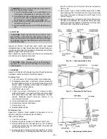
nuts, attach the DAT to the 2 black wires that were
connected to the economizer board in Step 18.
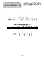
20. Using the wire tie provided, attach the DAT to the in-
door blower as shown in Fig. 30.
21. To test the unit, jumper terminals 1 and 3 of the OAT.
When power is applied and there is a call for cooling,
the economizer will be fully open.
22. After testing, slide outdoor-air inlet screens into screen
track on hood side plates. Clamp screens together us-
ing clasp provided. While holding screens in place, fas-
ten screen retainer to hood using screws provided.
23. Replace control box cover, indoor-fan motor access pan-
els, and compressor access panel using screws saved
in Step 19.
MINIMUM
POSITION
OPEN
3
1
T
P
P1
T1
4
2
5
S
S
O
D
C
TR
B
REV
. B
198818A
%
H
U
M
I
D
I
T
Y
90
70
60
30
10
D
C
B
A
60
65
70
75
55
50
85
80
DAMPER
DAMPER
CLOSED
OPEN
OUTDOOR TEMP
.
°
F
REV.
97-3672
CW–SETPOINTS–CCW
CONT
A
CTS SHO
WN IN HIGH ENTHALPY
RUSH A
T
24V
AC
3 mA
MIN.
A
T
1
1
VDC
CONT
ACT RA
TINGS: 1.5A
RUN, 3.5A
IN
OR UNPOWERED ST
A
T
E
1
2
3
TR
TR1
24V
AC
ENTHALPY
CONTROL
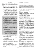
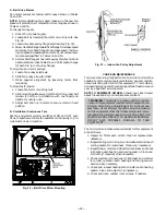
Fig. 27 — Outdoor-Air Thermostat/
Enthalpy Control Installation
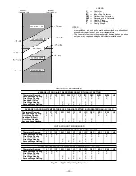
Fig. 28 — Wiring Connections for
Outdoor-Air Thermostat
PLUG 4
MOUNTING
SCREWS
DISCHARGE-AIR
THERMISTOR
CONNECTIONS
TERMINAL STRIP
BOARD
CONNECTOR
ECONOMIZER
HARNESS
THERMOSTAT
CONNECTION
PLUG
MOUNTING
SCREW
ECONOMIZER
CONTROL BOARD
MOUNTING
SCREW
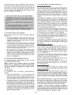
Fig. 29 — Economizer Board Installed
DISCHARGE-AIR
THERMISTOR LOCATION
Fig. 30 — Discharge-Air Thermistor (DAT) Location
—17—


