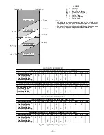
MAXIMUM ALLOWABLE
DIFFERENCE
A-B
B-C
A-C
mm
In.
mm
In.
mm
In.
13
.5
25
1.0
25
1.0
Fig. 5 — Unit Leveling Tolerance
UNIT
MAX
‘‘A’’
‘‘B’’
‘‘C’’
WEIGHT
Lb
Kg
In.
mm
In.
mm
In.
mm
548C090
840
381
77.42
1967
41.50
1054
42.12
1070
548C120
940
426
77.42
1967
41.50
1054
50.12
1273
NOTES:
1. Dimension in (
) is in millimeters.
2. Hook rigging shackles through holes in base rail, as shown in detail ‘‘A’’. Holes in base rails are
centered around the unit center of gravity. Use wooden top skid when rigging to prevent rigging
straps from damaging unit.
3. Weights do not include economizer. See Tables 1a and 1b for economizer weights.
CAUTION:
All panels must be in place when rigging.
Fig. 6 — Rigging Details
—5—


