


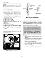
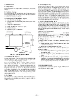


13. Connect OAT per Fig. 28.
14. Open main unit control box and remove inner control
box cover. Mount economizer control board in the low-
voltage section using 4 screws located in the control
box (see Fig. 29).
15. Connect plug from the economizer to plug on the econo-
mizer control board.
16. Connect plug 4 from the economizer board to connec-
tor on terminal strip board.
17. Connect thermostat wires to the orange plug provided
on the economizer board.
18. Attach the 2 black discharge-air thermistor (DAT) wires
to the economizer board.
NOTE:
A 2-stage cooling thermostat must be installed in con-
junction with the economizer to have an integrated econo-
mizer with mechanical cooling operation. A single-stage ther-
mostat will have economizer operation only.
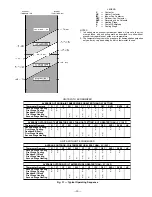
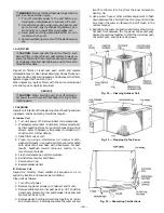
Fig. 22 — Block-Off Plate Location
NOTCH IN INDOOR COIL
BLOCK-OFF PLATE
TWO-POSITION
DAMPER PLUG
BAROMETRIC
RELIEF DAMPER
MOUNTING SCREWS
POSITION SETTING
BRACKET
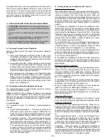
Fig. 23 — Economizer or Two-Position Damper
Installed in Unit
BAROMETRIC
RELIEF DAMPER
ECONOMIZER
MOTOR
CONDENSER
SECTION
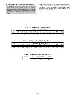
Fig. 24 — Horizontal Economizer Installation
OUTDOOR AIR HOOD PARTS
LOCATED BEHIND THIS PANEL
BLOCK-OFF PLATE
Fig. 25 — Horizontal Discharge Block-Off Plate
POSITION
SETTING
BRACKET
TOP
SCREW
Fig. 26 — Position Setting Bracket
—16—


