


Accessory Economizer and Two-Position Damper
The economizer/two-position damper hood assembly is pack-
aged and shipped in the accessory. Accessory filter door pack-
age (part number 389031-201 on 090 units, and part number
389031-202 on 120 units) must be used with economizer and
two-position damper. Damper blades and control boards are
shipped with the accessory package.
1. Determine quantity of ventilation air required for build-
ing. Record amount of air for use in Step 8.
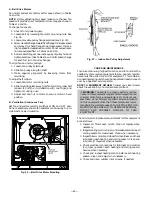
2. Remove indoor coil access panel (see Fig. 16). Discard
panel and use accessory filter door package instead (part
number 389031-201 on 090 units, and part number
389031-202 on 120 units). Fig. 17 shows the accessory
filter door package.
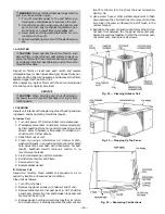
3. Assemble outdoor-air hood top and side plates as shown
in Fig. 18. Install seal strips on hood top and sides.
Put aside screen retainer and screws for later assem-
bly. Do not attach hood to unit at this time.
4. Install block-off plate over duct openings (see Fig. 22).
5. Slide economizer into unit and secure screws (see
Fig. 23). Remove screws securing barometric relief
damper, if desired.
6. To convert to horizontal discharge application:
a. Rotate economizer 90 degrees until economizer mo-
tor faces condenser section (see Fig. 24).
b. Rotate barometric relief damper 90 degrees so that
it opens and closes vertically.
c. Install horizontal discharge block-off plate over open-
ing on the access panel. Block-off plate MUST be
installed before installing hood assembly (see
Fig. 25).
IMPORTANT:
Filters MUST be installed outside the unit on
horizontal discharge applications with economizer or two-
position damper. Otherwise, the economizer or two-position
damper will have to be partially removed to access the fil-
ters. The area of the field-installed filters should be equal to
the area of the factory-installed filters.
7. Insert economizer plug from the wiring harness sup-
plied with the unit into the wiring harness plug sup-
plied with the economizer.
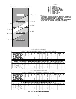
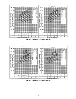
8. Determine damper position setting (see Fig. 19). Ad-
just damper setting by adjusting screws on the posi-
tion setting bracket (see Fig. 23). Slide position setting
bracket (see Fig. 26) until the top screw is in the posi-
tion determined by Fig. 19. Tighten screws.
9. Install accessory filter access door with screws saved
from Step 3.
10. Fasten hood top and side plate assembly and bottom
stop to unit with screws provided with accessory filter
access door (see Fig. 21).
11. Remove tape from outdoor-air thermostat (OAT).
Fasten OAT to inside of hood using screws and speed
clips provided (see Fig. 27). Make sure OAT terminals
are up.
12. Place knob supplied with economizer on OAT. Set for
3° F below indoor room thermostat setting. If acces-
sory solid-state enthalpy control (EC) is used instead
of the OAT, see instructions shipped with EC for in-
stallation and adjustment.
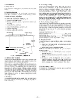
Fig. 16 — Access Panel Location
Fig. 17 — Accessory Filter Access Door
Fig. 18 — Outdoor-Air-Hood Details
—14—


