background image

III-71

(5)

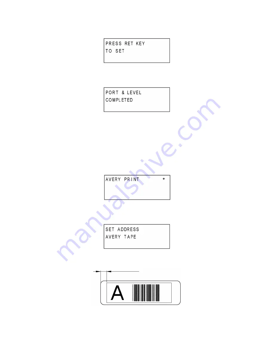
Press the “RET” key.  The display shifts to one as shown in Fig.37.

Fig. 37

(6)

Press the “RET” key.  The display shifts to one as shown in Fig.38.

Note 3: Here, if returns to the display as shown in Fig.35, restart from the step (2).

Fig. 38

(7)

Press the “RET” key while the LCD displays as shown in Fig.38.  The display shifts to
the Avery Print Mode as shown in Fig.39.

2.11. Avery Print Mode ( “ 9 “ key )

This mode verifies the start position of printing area of the print sample of the avery cassette.

Note 1: This mode is used only for PT-9600 and PT-3600 (U.S.A. version).

Note 2: Make sure to use an address labels cassette.  Do not use any types of cassettes

other than the avery cassette.

Fig. 39

(1)

Press the “RET” key.  The display shifts to one as shown in Fig.40.

(2)

Set the address labels cassette to the machine and close the cassette cover.

Fig. 40

(3)

Press the “RET” key.  The machine starts to print.

Print Sample 2

5±1.5mm

56.7±2.8mm

Summary of Contents for P-touch PT-3600

Page 1: ...SERVICE MANUAL MODEL PT 9600 3600 ...

Page 2: ...SERVICE MANUAL MODEL PT 9600 3600 ...

Page 3: ...always in best condition for the customer the service personnel must adequately understand and apply this manual This manual is made up of four chapters and appendices CHAPTER I SPECIFICATIONS CHAPTER II THEORY OF OPERATION CHAPTER III DISASSEMBLY AND REASSEMBLY CHAPTER IV TROUBLESHOOTING AND ERROR MESSAGE APPENDICES 1 MAIN PCB CIRCUIT DIAGRAMS 2 LCD PCB CIRCUIT DIAGRAMS Copyright Brother 2002 All...

Page 4: ... 1 3 2 Demonstration Print I 10 CHAPTER II THEORY OF OPERATION II 1 2 1 OUTLINE OF MECHANISMS II 1 2 1 1 Print Mechanism II 1 2 1 2 Roller Holder ASSY Setting Retracting Mechanism II 3 2 1 3 Tape Ribbon Feed Mechanism II 4 2 1 4 Tape Automatic Full Cutter Mechanism II 6 2 1 5 Tape Automatic Half Cutter Mechanism II 7 2 1 6 Tape Eject Mechanism Full Cut Only II 8 2 1 7 Release Button II 9 2 1 8 Rol...

Page 5: ... 9 Removing the Main PCB III 23 10 Removing the LCD Module Unit III 24 11 Removing the Release Button Tape End Sensor PCB and Cassette Sensor PCB III 26 3 2 REASSEMBLY PROCEDURE III 29 1 Reassembling the Cassette Sensor PCB Tape End Sensor PCB and Release Button III 29 2 Reassembling the LCD Module Unit III 32 3 Reassembling the Main PCB III 35 4 Reassembling the Components of the Chassis Unit III...

Page 6: ...cific dots omitted IV 40 2 The tape cassette type is not detected correctly IV 41 3 No printing is performed IV 42 4 The interface malfunctions RS 232C IV 42 5 The Interface malfunctions USB IV 43 6 The tape is not fed correctly IV 44 7 The tape is not cut IV 46 8 Half cut failure IV 47 9 Forced tape eject failure IV 48 Appendix 1 MAIN PCB CIRCUIT DIAGRAM Appendix 2 LCD PCB CIRCUIT DIAGRAM ...

Page 7: ...I 1 CHAPTER I SPECIFICATIONS 1 1 MECHANICAL SPECIFICATIONS 1 1 1 External Appearance Fig 1 1 1 External Appearance 1 PT 9600 Europe PT 9600 3600 U S A CANADA ...

Page 8: ... 9600 PT 3600 U S A 2 Number of alphanumeric and symbol keys 39 3 Number of function keys 27 PT 9600 21 PT 3600 U S A 19 PT 3600 Europe excluding ON OFF key PRINT key 4 Key arrangement See Fig 1 1 2 1 1 3 Display 1 Display type Liquid crystal display LCD PT 9600 having Back light 2 Configuration See Fig 1 1 2 119 dots wide by 24 dots high and guidance 3 Number of indicators See Fig 1 1 2 32 4 Fiel...

Page 9: ...07 11 40 x 31 2 8 x 2 17 40 146 x 112 10 22 x 7 84 12 44 x 34 3 08 x 2 38 48 175 x 135 12 25 x 9 45 14 51 x 39 3 57 x 2 73 56 204 x 157 14 28 x 10 99 16 58 x 45 4 06 x 3 15 64 234 x 179 16 38 x 12 53 18 66 x 50 4 62 x 3 5 72 263 x 201 18 41 x 14 07 20 73 x 56 5 11 x 3 92 76 277 x 213 19 39 x 14 91 Scaling with width settings WIDE 2 NARROW 2 3 NARROWEST 1 2 1 1 5 Tape Cassette 1 Cassette Cartridge ...

Page 10: ...d adhesive base tape PT 3600 U S A version Laminated tape cassette containing a 24 mm wide black ink ribbon laminated tape and adhesive base tape and AV address labels cassette containing a24 mm wide AV labels tape and base tape 1 1 6 Tape Cutter 1 Tape cutting 1 Automatic full cutter 2 Automatic half cutter Not user replaceable 1 and 2 1 1 7 PC Interface 1 Comunication Interface USB Serial interf...

Page 11: ...I 5 PT 9600 U S A CANADA PT 9600 U K Fig 1 1 2 Key Arrangement 1 ...

Page 12: ...I 6 PT 9600 German PT 9600 French Fig 1 1 2 Key Arrangement 2 ...

Page 13: ...I 7 PT 9600 Belgium PT 3600 U S A Fig 1 1 2 Key Arrangement 3 ...

Page 14: ...I 8 PT 3600 U K PT 3600 German Fig 1 1 2 Key Arrangement 4 ...

Page 15: ...I 9 PT 3600 French PT 3600 Belgium Fig 1 1 2 Key Arrangement 5 ...

Page 16: ...nerate DC voltage by the switching regulator in the machine The power supply cord is inserted into an inlet The protect circuit for the opposite polarity AC adapter is provided 2 Storage battery Dedicated Ni MH storage battery BA9600 PT 9600 only 3 Automatic powering off Yes Normal mode 5 min 30sec IF mode 30 min 30sec 1 3 KEY COMMANDS FOR SPECIAL FUNCTIONS 1 3 1 Initializing No powering on the ma...

Page 17: ...pe cassettes Instant lettering tape when using instant lettering tape cassettes Iron on transfer tape when using iron on transfer tape cassettes Cloth tape when using cloth tape cassettes Thermal tape when using AV Avery labels cassettes When using AV labels cassettes or stamp tape cassettes no ink ribbon is sandwiched For tape cassettes except stamp tape cassettes and AV labels cassettes If the s...

Page 18: ... generate a mirror image so that the printed character can be seen normally when viewed from the other side of the printed face of the tape Character Formation While the tape feed motor feeds the tape and ink ribbon only the tape when using AV labels cassettes or stamp tape cassettes by 0 0705 mm the thermal head generates heat once The feed amount is determined by sending five pulses of the signa...

Page 19: ...ing AV labels cassettes or stamp tape cassettes sandwiched inbetween under a uniform load by the platen spring At the same time the platen gear becomes engaged with the platen idle gear Also the tape feed sub roller is pressed perpendicularly against the tape feed roller built in the tape cassette with the tape and base paper when using laminated tape cassettes or stamp tape cassettes sandwiched i...

Page 20: ...As the tape feed motor stepping motor rotates the rotation is transmitted via the gear train to the platen idle gear which rotates the platen gear and the tape feed gear which rotates the tape feed roller and the tape feed sub roller at the same rotation speed Accordingly the sandwiched tape and ink ribbon will be advanced When a laminated tape cassette is mounted the sandwiched laminated tape adh...

Page 21: ... rotates counterclockwise When fitted on the ribbon drive cam the ribbon take up roll in the tape cassette also rotates to take up the ink ribbon To apply proper tension to the ink ribbon between the platen and the ribbon drive cam the feed amount of the ribbon drive cam is slightly greater than that of the tape feed gear The difference between the feed speeds at the platen and at the ribbon drive...

Page 22: ... lead shaft where the carriage is moved between them When the tape is cut the carriage is placed on the home position on the lower sensor first and then the lower sensor rotates the cutter motor while the sensor is being turned ON so that the carriage is moved in the direction of tape cutting When the upper sensor detects the carriage it is turned ON and the cutter motor is rotated in reverse Then...

Page 23: ...and forth through the tape control crank and tape control link The amount how much the cutter blade bites into the tape between the tape pressure and control plate is decided depending on the amount how much the tape pressure presses the control plate For half cutter the tape is cut so that only the peeling line is remained as shown in Fig Fig 2 1 6 Tape Automatic Half Cutter Mechanism Half cutter...

Page 24: ...he tape pressure is released and the eject shaft is rotated at the same time so that the tape fixed by the eject rubber and eject roller is ejected The eject shaft is rotated by the eject motor The rotation of the eject shaft is synchronous with the movement that the tape pressure is released Fig 2 1 7 Tape Eject Mechanism Full Cut Only Cassette tape Cut Control plate Eject rubber Eject roller hol...

Page 25: ...ection 2 1 2 Roller Holder ASSY Setting Retracting Mechanism the roller release lever shifts the roller holder release rod so that the roller holder ASSY is pressed towards the head ASSY side Fig 2 1 9 Roller Release Lever and Roller Holder Release Rod Release button Lock arm Shaft Head ASSY Tape cassette Roller holder ASSY engaged Roller holder ASSY retracted Roller holder release rod Roller hold...

Page 26: ...se lever placed in the hooked section of the cassette cover which shifts the roller holder release rod so that the roller holder ASSY is retracted from the head ASSY side by the roller holder release spring Cassette cover sensor tab Closing Opening Release button Lock arm Hook Cassette cover Cassette cover sensor tab Lock arm ...

Page 27: ... to the AV print position sensor the sensor receives no reflected light signaling the print start position 1 Pressing the Print key will start tape feeding 2 When a lower black detection mark on the back of an AV labels tape comes to the AV print position sensor printing will start 3 When the printed label exits from the tape cutter position tape feeding will stop The AV labels tape will be automa...

Page 28: ... also switches that the cutter carriage goes up and down by its rotating and reversing Eject Motor The eject motor ejects the cut tape Thermal Head The thermal head has 384 dots x 1dots 360dpi thin film configuration and incorporates a drive circuit The drive voltage is VH 24V Cutter Sensor PCB 1 2 The cutter sensor PCBs 1 2 detect the position of the cutter carriage Cassette Cover Open Sensor PCB...

Page 29: ...3 LED PCB PT 9600 The LED for the back light is mounted on the LED PCB Navi Dial PCB European versions The navi dial switch is mounted on the Navi dial PCB Fig 2 2 1 Block diagram of the control electronics ...

Page 30: ...emperature detect circuit 14 Head temperature detect circuit 15 AC adapter detect circuit 16 Storage battery voltage detect circuit PT 9600 only 17 AV sensor circuit excluding PT 3600 Europe model 18 AV cassette sensor circuit excluding PT 3600 Europe model 19 LCD driver 20 Power supply circuit 21 Key solder point detect circuit 22 RS 232C USB interface circuit RS 232C PT 9600 only 23 RTC drive ci...

Page 31: ...II 15 Fig 2 2 2 Block Diagram of Main PCB ...

Page 32: ...rough CSNS4 and AV cassette sensor AVSW Loading a tape cassette turns on some of those five switches on the cassette sensor while keeping other switches off depending upon the ID encoding holes provided in the tape cassette currently loaded If an encoding ID hole is closed the corresponding sensor switch goes on The AV cassette sensor AVSW is provided for distinguishing AV labels cassettes from TZ...

Page 33: ...tamp tape cassette L 1 0 1 1 0 0 Non laminated tape cassette 1 0 0 0 0 0 Instant lttering tape cassette Iron on transfer tape cassette 1 1 1 0 1 0 24mm Laminated tape cassette 1 0 1 1 1 0 Non laminated tape cassette 1 0 0 0 1 0 36mm Laminated tape cassette 0 0 0 1 0 0 Non laminated tape cassette 0 0 0 0 1 0 24mm Address labels cassette 1 0 1 0 0 1 Return address labels cassette 1 0 0 1 1 1 AV File...

Page 34: ...ICs U1 U4 controlling the LCD and LCD display are mounted on the LCD PCB The LCD PCB receives the display data to be sent from the main PCB and displays it on the LCD For the details on the circuit diagram refer to Appendix 2 ...

Page 35: ...0 LCD support LCD holder Taptite bind B M2 6x8 4 39 2 10 4 0 1 0 Bottom cover Taptite bind B M2 6x10 12 39 2 10 4 0 1 0 Chassis ASSY Taptite bind B M2 6x8 3 39 2 10 4 0 1 0 Half frame unit Screw bind M3x6 4 58 8 10 6 0 1 0 Main PCB Screw bind B M2 6x8 5 39 2 10 4 0 1 0 Tape guide Screw bind M3x6 1 58 8 10 6 0 1 0 AV cassette sensor ASSY Screw pan M1 7x6 1 14 7 5 1 5 0 5 Cutter sensor ASSY Screw pa...

Page 36: ...CEDURE 1 Removing the Tape Cassette 1 Push the release button and open the cassette cover fully 2 Pull the tape cassette up and out of the machine Fig 3 1 1 Removing the Tape Cassette Release button Cassette cover ASSY Cassette ...

Page 37: ...e hooks of both sides and push the two pins outward as shown in the figure below to remove the cassette presser from the cassette cover ASSY 3 Remove the two cassette presser springs from the cassette cover ASSY Fig 3 1 3 Removing the Cassette Cover ASSY 2 Cassette cover ASSY Hinge Hinge Hook Pin Pin Hook Cassette presser spring Cassette cover ASSY Cassette presser spring Cassette presser ...

Page 38: ...attery lid PT 9600 only 3 Disconnect the connector to remove the battery PT 9600 only Fig 3 1 4 Removing the Screw from Bottom Cover 1 3 Remove the twelve screws from the bottom cover 4 Turn the machine up Fig 3 1 5 Removing the Screw from Bottom Cover 2 Hooks Battery lid Bottom cover Battery Screws Bottom cover Screws ...

Page 39: ... and disconnect the FPC cable 4 Turn the KB unit or rubber key unit over and remove a screw to detach the FG wire A and the KB unit or rubber key unit PT 9600 PT 3600 U S A CANADA only 5 Pull the FPC cable out of the ferrite core PT 9600 PT 3600 EU only 6 Remove the KB unit or rubber key unit Fig 3 1 6 Removing the KB Unit Rubber Key Unit FG wire A PT 9600 PT 3600 U S A CANADA only FG wire A PT 96...

Page 40: ...0 PT 3600 U S A 3 Remove the key C RET wire from the key C PT 9600 PT 3600 U S A Note Be sure not to break the hooks on the key when removing the wire 4 Remove the key D SP wire from the key D PT 9600 PT 3600 U S A Note Be sure not to break the hooks on the key when removing the wire Fig 3 1 7 Disassembling the KB Unit Rubber Key Unit 1 Key D KB unit Hooks Hooks Hooks Key C Key C RET wire Key C Ke...

Page 41: ...e jog dial from the KB unit or rubber key unit EU only Fig 3 1 8 Disassembling the KB Unit Rubber Key Unit 2 7 Remove the job dial from the jog PCB ASSY EU only Fig 3 1 9 Disassembling the KB Unit Rubber Key Unit 3 KB unit or rubber key unit Screw Jog dial Jog PCB ASSY Screws Screw Jog PCB ASSY Jog dial ...

Page 42: ...dy KB cover Fig 3 1 10 Disassembling the KB Unit Rubber Key Unit 4 9 Remove the PCB from the body KB cover Fig 3 1 11 Disassembling the KB Unit Rubber Key Unit 5 Screw No screw for U S A spec Body KB cover Screw No screw for EU spec Screw Hooks Hooks Hooks PCB Fix plate Screws Body KB cover PCB ...

Page 43: ... cover PT 9600 PT 3600 U S A only Fig 3 1 12 Disassembling the KB Unit Rubber Key Unit 6 11 Remove the rubber key from the body KB cover PT 9600 EU only Fig 3 1 13 Disassembling the KB Unit Rubber Key Unit 7 Body KB cover Contact rubber Function rubber Body KB cover Rubber key ...

Page 44: ... the release position before removing the body cover 2 Lift and hold the body cover while disconnecting the LCD PCB cable the tape end sensor cable and the cassette sensor cable from the main PCB ASSY 3 Remove the body cover Fig 3 1 14 Removing the Body Cover Body cover Cassette sensor cable Bottom cover Main PCB ASSY LCD PCB cable Hooks Tape end sensor cable Hooks ...

Page 45: ...or harness PT 9600 PT 3600 U S A only AV sensor harness PT 9600 PT 3600 U S A only Thermal head harness 2 Remove three screws from the chassis unit Detach the FG wire C of the main PCB from the chassis unit 3 Remove the chassis unit from the bottom cover Fig 3 1 15 Removing the Chassis Unit FG wire C Bottom cover Thermal head harness AV cassette sensor harness Carriage motor harness Cutter sensor ...

Page 46: ...move a screw to remove the eject unit from the chassis unit Fig 3 1 16 Removing the Eject Unit 1 2 Remove a screw to remove the eject shaft spring from the eject unit Fig 3 1 17 Removing the Eject Unit 2 Screw Eject unit Chassis unit Eject unit Eject shaft spring Screw ...

Page 47: ...ide Fig 3 1 18 Removing the Eject Unit 3 4 Remove the eject rubber from the eject roller shaft 5 Remove the eject gear from the eject roller shaft Fig 3 1 19 Removing the Eject Unit 4 Eject roller ASSY Tape guide Eject rubber Eject gear Eject roller shaft ...

Page 48: ...s the back of the head roller holder unit to remove it Note First ensure to push the roller holder in the direction shown by the arrow and then remove it from the head roller holder unit Fig 3 1 20 Removing the Head Roller Holder Unit Head roller holder unit Screws Chassis ASSY ...

Page 49: ...Fig 3 1 21 Removing the Half Cutter Chassis ASSY 1 2 Remove two screws to remove the HC support plate from the half cutter chassis ASSY 3 Remove two screws to remove the cutter sensor PCB ASSY from the half cutter chassis ASSY Fig 3 1 22 Removing the Half Cutter Chassis ASSY 2 Chassis ASSY Half cutter chassis ASSY Screws Screws Cutter sensor PCB ASSY Half cutter chassis ASSY HC support plate Screw...

Page 50: ... Feed Motor Removing the Double Gear 1 and Eject Idle Gear 1 Remove the components from the chassis ASSY in such the order as the retaining ring the double gear 1 and the eject idle gear Fig 3 1 24 Removing the Double Gear 1 and Eject Idle Gear Chassis ASSY Screws Tape feed motor Retaining ring Double gear 1 Chassis ASSY Eject idle gear ...

Page 51: ...chassis ASSY Fig 3 1 25 Removing the Eject Motor ASSY Removing the Tape Control Motor ASSY 1 Remove two screws to remove the tape control motor ASSY from the chassis ASSY Fig 3 1 26 Removing the Tape Control Motor ASSY Chassis ASSY Screws Eject motor ASSY Tape control motor ASSY Chassis ASSY Screws ...

Page 52: ...tor unit from the chassis ASSY Fig 3 1 27 Removing the Carriage Motor ASSY 1 2 Remove two screws and detach the HC motor holder from the carriage motor ASSY Fig 3 1 28 Removing the Carriage Motor ASSY 2 Carriage motor unit Screw Chassis ASSY Carriage motor ASSY HC motor holder Screws ...

Page 53: ...roller release rod 4 As the release rod roller is secured in place by the elasticity of the resin of the roller release rod press the shaft of the release rod roller to remove it from the roller release rod Fig 3 1 29 Removing the Roller Release Rod Roller release rod Release rod roller Release lever spring Retaining ring Release lever Chassis ASSY Release rod Release rod roller ...

Page 54: ...g the AV Sensor Actuator AV Cassette Sensor ASSY 1 2 Take the AV sensor actuator and the AV sensor spring off the chassis ASSY along the shaft slot shape of the chassis 3 Remove the AV sensor spring from the AV sensor actuator Fig 3 1 31 Removing the AV Sensor Actuator AV Cassette Sensor ASSY 2 Screw AV cassette sensor ASSY Chassis ASSY AV sensor actuator AV sensor spring Chassis ASSY ...

Page 55: ...ot touch the platen rubber doing so may adversely affect the printing quality Fig 3 1 32 Disassembling the Head Roller Holder Unit 1 3 Remove the roller holder release spring Note Take care not to lose the roller holder release spring which is removed simultaneously when the roller holder ASSY is removed Fig 3 1 33 Disassembling the Head Roller Holder Unit 2 Retaining ring Roller holder shaft Head...

Page 56: ...III 22 4 Remove a screw to remove the AV sensor PCB from the roller holder ASSY PT 9600 PT 3600 U S A only Fig 3 1 34 Disassembling the Head Roller Holder Unit 3 Screw Roller holder ASSY AV sensor PCB ...

Page 57: ...00 only and the USB connector from the slots of the bottom cover Fig 3 1 35 Removing the Main PCB 1 2 Remove the sheet A from the bottom cover 3 Remove the shield plate D from the bottom cover Fig 3 1 36 Removing the Main PCB 2 Serial connector PT 9600 only USB connector Bottom cover Main PCB Screws Screws Sheet A Bottom cover Shield plate D ...

Page 58: ...m the body cover Fig 3 1 37 Removing the LCD Module Unit 1 2 Release the hooks A in three places to remove the light plate ASSY from the LCD module unit PT 9600 only Fig 3 1 38 Removing the LCD Module Unit 2 Body cover LCD module unit Screws Screws Hook A Light plate ASSY LCD module unit Hook A ...

Page 59: ...PCB ASSY are connected PT 9600 only 5 Detach the diode SLR 342MC on the LCD PCB ASSY from the LCD PCB ASSY by melting solder PT 9600 only 6 Release the hooks C in four places to detach the LCD holder from the LCD PCB ASSY PT9600 only Fig 3 1 39 Removing the LCD Module Unit 3 Leads three harnesses Diode Hook B LCD PCB ASSY LCD holder LED PCB ASSY LCD PCB ASSY Hook B LCD holder Hook C LCD PCB ASSY ...

Page 60: ... releasing the hook that fixes it on the body cover in order to remove the lock arm Fig 3 1 40 Removing the Lock Arm Spring and Lock Arm 3 Release the hooks in four places to remove the release button from the body cover Fig 3 1 41 Removing the Release Button Lock arm Body cover Hook Body cover Lock arm Lock arm spring Body cover Hooks Release button Hooks ...

Page 61: ...release button Fig 3 1 42 Removing the Release Button Spring 5 Remove two screws to remove the tape end sensor PCB from the body cover Fig 3 1 43 Removing the Tape End Sensor PCB Release button spring Release button Screws Tape end sensor PCB Body cover ...

Page 62: ...III 28 6 Release the hooks in three places to remove the cassette sensor PCB from the body cover Fig 3 1 44 Removing the Cassette Sensor PCB Cassette sensor PCB Hooks Body cover ...

Page 63: ...lot of the body cover Note Make sure to embed the PCB by the hooks in three places of the body cover 3 Push and release each switch to verify their normal reaction Fig 3 2 1 Reassembling the Cassette Sensor PCB 4 Reassemble the tape end sensor PCB with the two screws into the body cover Fig 3 2 2 Reassembling the Tape End Sensor PCB Cassette sensor PCB Cover open detection switch Tape cassette typ...

Page 64: ...to full around the stem and the stem head of the release button Fig 3 2 3 Reassembling the Release Button 1 6 Reassemble the release button on the body cover Note Make sure to secure the hooks of the release button in four places of the body cover Fig 3 2 4 Reassembling the Release Button 2 Release button Apply grease Release button spring Hooks Hooks Body cover Release button ...

Page 65: ... 8 Reassemble the lock arm spring on the lock arm to be effect against the body cover as shown below Note Apply the silicon grease Shin Etsu Chemical brand G501 by a half rice grain sized drop on each B portion of lock arm Fig 3 2 5 Reassembling the Lock Arm and Lock Arm Spring B Body cover B A Body cover Lock arm Hook Lock arm spring Lock arm ...

Page 66: ...CD holder to the LCD PCB ASSY with the hooks C in four places and two pins Note Handle the LCD flexible cable carefully not to put any damage on it Fig 3 2 6 Reassembling the LCD Module Unit 1 LCD Holder Pin LCD flexible cable Hook C Hook C Pin LCD PCB ASSY ...

Page 67: ... LED PCB ASSY through the slot of the LCD holder and solder it to the LCD PCB ASSY PT 9600 only Note Solder the leads three harnesses to the LCD PCB ASSY in accordance with the color indications on the LCD substrate Fig 3 2 7 Reassembling the LCD Module Unit 2 5 Reassemble the light plate ASSY to the LCD module unit fixing with the hooks in three places Fig 3 2 8 Reassembling the LCD Module Unit 3...

Page 68: ... Fit the LCD module unit on the pin shown in the figure below and secure four screws to assemble it into the body cover Fig 3 2 9 Reassembling the LCD Module Unit 4 Body cover Pin LCD module unit Screws Screws ...

Page 69: ...assembling the Main PCB 1 3 First insert the serial connector PT 9600 only and the USB connector to the slots of the bottom cover Then secure the main PCB on the bottom cover with five screws Fig 3 2 11 Reassembling the Main PCB 2 Sheet A Bottom cover Pin Pin Shield plate D Screws Bottom cover Serial connector PT 9600 only USB connector Main PCB Screws ...

Page 70: ...it 1 Connect the AV sensor PCB with the roller holder ASSY with a single screw PT 9600 PT 3600 U S A only Note Pay attention not to have the AV sensor PCB harness between the substrate and the screw boss Fig 3 2 12 Reassembling the Head Roller Holder Unit 1 Roller holder ASSY AV sensor PCB Screw ...

Page 71: ...se Shin Etsu Chemical brand G501 by a quarter rice grain sized drop with a brush on each end of platen shaft Note 3 Pass the AV sensor harness over the roller holder release spring as indicating in A shown below when assembling the roller holder ASSY to the head ASSY Fig 3 2 13 Reassembling the Head Roller Holder Unit 2 4 Insert the roller holder shaft from the bottom of the head ASSY then secure ...

Page 72: ...ote Verify after the assembly whether the AV sensor actuator moves without a hitch Fig 3 2 15 Reassembling the AV Sensor Actuator 1 3 Assemble the AV cassette sensor ASSY on the chassis ASSY with a screw after fitting the positioning pin of the sensor ASSY in the slot A of the chassis ASSY Fig 3 2 16 Reassembling the AV Sensor Actuator 2 AV sensor actuator AV sensor spring Chassis ASSY Screw AV ca...

Page 73: ...ure them using the retaining ring Note Apply the silicon grease Shin Etsu Chemical brand G501 by a rice grain sized drop to the rubbing portion between the roller release rod and the release lever 3 Hook the end of the release lever spring on the hole of the release lever Hook the other end of the release lever spring on the tab of the chassis ASSY Fig 3 2 17 Reassembling the Roller Release Rod Ap...

Page 74: ...ASSY Fig 3 2 18 Reassembling the Carriage Motor ASSY 1 2 Assemble the carriage motor ASSY on the chassis ASSY with a screw Note Fit the holes on the HC motor holder in two places first to the two positioning bosses of the back of chassis ASSY and then secure the screw Fig 3 2 19 Reassembling the Carriage Motor ASSY 2 A Screws HC motor holder Carriage motor ASSY Positioning bosses Holes Carriage mo...

Page 75: ...is ASSY with two screws Fig 3 2 20 Reassembling the T Control Motor ASSY Reassembling the Eject Motor ASSY 1 Assemble the eject motor ASSY on the chassis ASSY with two screws Fig 3 2 21 Reassembling the Eject Motor ASSY Tape control motor ASSY Chassis ASSY Screws Eject motor ASSY Screws Chassis ASSY ...

Page 76: ...ar 1 on the chassis ASSY in this order Fig 3 2 22 Reassembling the Eject Idle Gear and Double Gear 1 Reassembling the Tape Feed Motor 1 Assemble the tape feed motor on the chassis ASSY with two screws Fig 3 2 23 Reassembling the Tape Feed Motor Retaining ring Double gear 1 Chassis ASSY Eject idle gear Screws Tape feed motor Chassis ASSY ...

Page 77: ...ing pins in two places and secure it on the chassis ASSY with six screws Warning Take care not to get injured in your fingers with the cutter blade Note Apply the silicon grease Shin Etsu Chemical brand G501 by a half rice grain sized drop with a brush on A portion of control plate Fig 3 2 25 Reassembling the Half Cutter Chassis ASSY 2 Positioning pin Positioning pin Positioning pin Screws Half cu...

Page 78: ...ssis ASSY with two screws Note Apply the silicon grease Shin Etsu Chemical brand G501 by a half rice grain sized drop when assembling to the main frame 3 Move the release lever to check for the correct operation of the head roller holder unit Fig 3 2 26 Installing the Head Roller Holder Unit Apply grease Head roller holder unit Thermal head harness AV sensor harness PT 9600 PT 3600 U S A only Chas...

Page 79: ...ssemble the eject roller ASSY on the tape guide Note Apply the silicon grease Shin Etsu Chemical brand G501 by a quarter rice grain sized drop to the both tips of the eject roller shaft Make sure not to apply the silicon grease to the eject rubber Fig 3 2 28 Reassembling the Eject Unit 2 Eject rubber Eject roller shaft Eject gear Apply grease Apply grease Eject roller ASSY Tape guide ...

Page 80: ... Reassembling the Eject Unit 3 5 Fit the positioning pin of the eject unit to the slit of the chassis ASSY and secure it to the chassis ASSY with a screw Fig 3 2 30 Reassembling the Eject Unit 4 Eject Unit Eject shaft spring Screw Positioning pin Eject unit Screw Slit Chassis ASSY ...

Page 81: ...e control motor harness Cutter sensor harness AV cassette sensor harness PT 9600 PT 3600 U S A AV sensor harness PT 9600 PT 3600 U S A Thermal head harness Note Apply the silicon grease Shin Etsu Chemical brand G501 by a half rice grain sized drop on each gears Fig 3 2 31 Installing the Chassis Unit 1 AV sensor harness PT 9600 PT 3600 U S A Boss AV cassette sensor harness PT 9600 PT 3600 U S A FG ...

Page 82: ...assette sensor PT 9600 PT 3600 U S A AV sensor PT 9600 PT 3600 U S A LCD cable Main PCB Keyboard FPC cable FG wire C Thermal head Carriage motor Cutter sensor Eject motor Cassette sensor Jog PCB EU only Tape end sensor Tape control motor Tape feed motor ...

Page 83: ...o the main PCB ASSY 2 Install the body cover to the bottom cover until confirming click noise sounds Note Pay attention not to have any cables and harnesses between the both covers when combining them Fig 3 2 33 Reassembling the Body Cover Cassette sensor cable Hooks LCD PCB cable Main PCB ASSY Bottom cover Tape end sensor cable Body cover Hooks ...

Page 84: ...B cover and assemble them PT 9600 PT 3600 U S A only Fig 3 2 34 Reassembling the KB Unit Rubber Key Unit 1 2 Fit the slots on the rubber key to the pins on the body KB cover and assemble them PT 3600 EU only Fig 3 2 35 Reassembling the KB Unit Rubber Key Unit 2 Body KB cover Pin Contact rubber Function rubber Body KB cover Pin Rubber key ...

Page 85: ...er Key Unit 3 4 Fit the fix plate to the hooks in ten places on the body KB cover and secure it to the body KB cover with five screws Fig 3 2 37 Reassembling the KB Unit Rubber Key Unit 4 Body KB cover PCB Hook Screw No screw for EU spec Screw Body KB cover Screw No screw for U S A spec Hooks Hooks Hooks PCB Fix plate Screws ...

Page 86: ...the jog PCB ASSY on the two pins and secure it to the KB unit or rubber key unit with three screws EU only 7 Secure the FG wire B of the jog PCB ASSY to the KB unit or rubber key unit EU only Fig 3 2 39 Reassembling the KB Unit Rubber Key Unit 6 Notch Jog PCB ASSY Jog dial KB unit or rubber key unit FG wire B Screw Pin Pin Jog PCB ASSY Screws Screw ...

Page 87: ...e on the key D PT 9600 PT 3600 U S A 10 Install the key C on the KB unit PT 9600 PT 3600 U S A 11 Install the key D on the KB unit PT 9600 PT 3600 U S A Fig 3 2 40 Reassembling the KB Unit Rubber Key Unit 7 Hooks Hooks Key D Key C Key D SP wire Key C RET wire Key D KB unit Hooks Hooks Hooks Key C ...

Page 88: ...insert the harness to the connector on the main PCB for EU spec only Note Exchange the cushion of the ferrite core if it is damaged 5 Assemble the KB unit or rubber key unit to the bottom cover with the hooks in eight places until confirming click noise sounds Note 1 Be sure not to catch the FG wire A between any hooks Note 2 Ensure that no harness rides on the support lib of the jog PCB for EU sp...

Page 89: ...contain the battery in the machine PT 9600 only 4 Fit the battery lid A to the slits of the bottom cover in three places and push the battery lid until the B can be nipped PT 9600 only Note Exchange the cushions of the battery lid if those are broken PT 9600 only 5 Turn the machine up Fig 3 2 43 Reassembling the Bottom Cover 2 Bottom cover Screws Screws Hook Cushion Battery lid Hole Battery Batter...

Page 90: ...ssette presser to the A portions of the cassette cover ASSY respectively and then insert the hooks of the cassette presser to the B portions of the cassette cover ASSY in two places Fig 3 2 44 Reassembling the Cassette Cover ASSY 1 Cassette presser spring Hook Hinge Hinge B A B Cassette cover ASSY Cassette presser spring Hook Cassette presser ...

Page 91: ...lling it Press the release button If the cassette cover opens fully without stopping at the expected stop position exchange the brake pad Note 2 After attaching brake pad apply the silicon grease Shin Etsu Chemical brand G501 by a half rice grain sized drop uniformly with a brush Fig 3 2 45 Reassembling the Cassette Cover ASSY 2 Apply grease Brake pad Cassette cover ASSY Hinge Hinge ...

Page 92: ... 58 11 Reassembling the Tape Cassette 1 Pull up the release lever 2 Install the tape cassette 3 Close the cassette cover Fig 3 2 46 Reassembling the Tape Cassette Release lever Cassette cover Tape cassette ...

Page 93: ...n modes Make good use of these modes in classifying into the modes to be applied and not to be applied according to the details of repairs Note 1 Depression of the mode selection key allows shifting to the other mode when you are in the initial level of every mode Note 2 The modes the latter half of Note 2 are also provided in addition to the modes listed below but are not applied for the inspecti...

Page 94: ...B Mode A key Full Cutter Adjustment Mode F key Tape Control Motor Excitation Phase Check Mode G key 2 1 Specification Change Mode 1 key This mode determines a country unique specification 1 Press the RET key while the LCD displays as shown in Fig 2 The display shifts to the Specification Change Mode as shown in Fig 3 Fig 3 2 Press the RET key The display shifts to one as shown in Fig 4 Fig 4 3 Sel...

Page 95: ...ress the RET key The machine reads the voltage writes it into the EEPROM and then shifts to the Sensor Check Mode as shown in Fig 7 2 3 Sensor Check Mode 3 key This mode checks the functions of any sensors Fig 7 1 Press the RET key The display shifts to one as shown in Fig 8 Fig 8 2 The machine checks the functions of the cassette sensor the die cut cassette sensor and the cover open sensor and di...

Page 96: ...nges to 1 or 1 If the density of the LCD is too high select 1 and if too thin select 1 Then press the RET key to write the selection into the EEPROM Note 1 If you select the default setting 0 the display shifts automatically to the Half Cutter Adjustment Mode Note 2 If you select 1 or 1 return to the step Fig 10 and repeat the steps until reaching the step Fig 12 Press the RET key at the end of th...

Page 97: ...ey and then the sample printing is started After the completion of printing the display returns to the initial display of the setting item selection Note 1 Press only the RET key to start the sample printing if you accept the default setting values Note 2 To determine the sample print quality set the feed length of the tape to 30 mm and reduce the step length from 200 to 160 by 5 steps The accepta...

Page 98: ...tep 185 5 is specified Fig 17 8 Press the 3 key The display shifts to the Half Cut Blade Length Adjustment Mode 9 Use the numeric keys to enter the central step number and the step length 10 Press the RET key to write the above entries into the EEPROM The machine execute three lines of half cut operation forward and backward around the central step number according to the specified step length as ...

Page 99: ... step numbers and the step length 5 Press the RET key to write the above entries into the EEPROM The machine execute three lines of full cut operation forward and backward around the central step number according to the specified step length as shown in Fig 22 After printing the display returns as shown in Fig 21 that enables to select the initial items Note If you accept the default settings pres...

Page 100: ...t the same time See the following table Table 1 showing the combinations of the number displayed on the LCD and the excitation phase of the motor LCD display 4 3 2 1 Excitation phase of motor CD DA AB BC Table 1 4 Press the 2 key to enter the mode to set the starting phase of the tape control motor 5 Use the numeric key to write the starting phase of the tape control motor into the EEPROM See the ...

Page 101: ... as shown in Fig 19 indicates a key to be pressed When the pressed key is proper it will indicate a next key to be pressed When the pressed key is not proper it will indicate the key to be pressed and also display X as shown in Fig 26 Fig 25 Fig 26 3 After the completion of full key check it displays as shown in Fig 27 and the machine prints the contents as shown in Fig 28 The detail of Fig 28 is ...

Page 102: ...0 6 The arrow sign or moves synchronizing with the rotating direction of the jog dial Press the Set key the central button of the jog dial when the arrow sign reaches the left by 3 points just above the first cursor at the left end in the left mode as shown in Fig 31 7 If any error is detected the machine displays as shown in Fig 32 8 When no error is confirmed the display shifts to the right mode...

Page 103: ...ues had not been written in the EEPROM the machine does not start to print 2 Verify the print quality and the print accuracy of the print sample Print Sample 1 2 10 Avery Detection Voltage Mode 8 key This mode reads the detection mark of the avery cassette and the reference voltage level of it and writes the voltage level into the EEPROM of the main PCB Note 1 This mode is used only for PT 9600 an...

Page 104: ...ress labels cassette is white Then set it to the machine and close the cassette cover Fig 35 3 Press the RET key The display shifts to one as shown in Fig 36 4 Remove the cassette Draw out the tape until the black section appears at the detection section of the address labels cassette Then replace the cassette and close the cassette cover Fig 36 A A ...

Page 105: ...ig 39 2 11 Avery Print Mode 9 key This mode verifies the start position of printing area of the print sample of the avery cassette Note 1 This mode is used only for PT 9600 and PT 3600 U S A version Note 2 Make sure to use an address labels cassette Do not use any types of cassettes other than the avery cassette Fig 39 1 Press the RET key The display shifts to one as shown in Fig 40 2 Set the addr...

Page 106: ...he RS I F port Note This mode is used only for PT 9600 Fig 42 1 Press the RET key The display shifts to one as shown in Fig 43 Fig 43 2 The machine checks the RS 232C I F port Displays RXD on the LCD 3 Press the RET key while the LCD displays as shown in Fig 43 The display shifts to the Clock Display Mode as shown in Fig 44 2 13 Clock Display Mode Q key This mode corrects the clock display accurat...

Page 107: ...r by every depression of the BL key 3 Press the RET key while the LCD displays as shown in Fig 47 The display shifts to the Margin Set Mode as shown in Fig 48 2 15 Avery Adjust Mode E key This mode sets the correction value of the print start position of avery tape Note 1 This mode is used only for PT 9600 and PT 3600 U S A version Note 2 You may skip this submode if the print sample by the Avery ...

Page 108: ...e left side by approx 4 5 mm 64 dots 9 key Example Corrects by about 1 0 mm to the left side Fig 50 3 If you want to set a plus correction value correct the current value according to one of the following key operations The result will be displayed as shown in Fig 51 To move the print start position by the following amount Press The correction value is displayed as 0 mm 0 key to the right side byY...

Page 109: ...into the specified zone Fig 53 1 Press the RET key The display shifts to one as shown in Fig 54 Fig 54 2 Press the 1 key and set the number of counter rotation pulses at the margin cut process 10 through 150 pulses Note 2 The number of counter rotation pulses is the number of counter rotation pulses after the print operation 3 Press the 2 key and set the number of superimposed dots at the margin c...

Page 110: ...d as shown in Fig 57 The display shifts to one as shown in Fig 58 Note 1 Key word is 3600 Fig 57 3 Display the default value 000000001 Note 2 If the serial number has been written into the PCB that value is displayed here 4 Enter the serial number of nine digits printed on the ID plate of the product Example Enter G1J497693 if the printed number is E60125 G1J497693 Fig 58 5 Press the RET key to wr...

Page 111: ...ke sure that its output voltage level Ni MH battery pack 9 12V AC adapter 23 25V under no load 3 When supplying power from a stabilized power unit use the power unit with approx 3A capacity and adjust the output level to the one as described above When connecting it to this machine be careful with the polarity 4 When using a circuit tester for testing the conductivity remove the Ni MH battery pack...

Page 112: ...using the batteries The batteries are weak Supplement After the operation is completed or the message is deleted the machine returns to the text input mode BATTERIES_WEAK PILES_USEES BATTERIEN_SCHWACH BATTERIES_WEAK PILES_USÉES While feeding the tape when using the batteries The batteries are weak Supplement After the operation is completed or the message is deleted the machine returns to the text...

Page 113: ...key The text buffer memory is full Auto format input mode When pressing a PF key The text buffer memory is full Function select mode When pressing the Set key or A Symbol or Accent is selected when the text buffer memory is full Supplement In insert mode after the message is deleted the machine returns to the text input mode Dead mode When pressing the Return key The text buffer memory is full in ...

Page 114: ... When pressing a Dead Character key The text buffer memory is full Template data input mode When pressing the Space key The text buffer memory is full Template data input mode When pressing the Symbol key The text buffer memory is full Template data input mode When pressing the Accent key The text buffer memory is full Template data input mode When pressing the PF key The text buffer memory is ful...

Page 115: ...r memory Menu select mode A F When pressing the Print key There is no data in the text buffer memory Menu select mode A F When pressing the Set key after selecting the Print key There is no data in the text buffer memory File number setting mode When pressing the Set Print keys There is no data in the text buffer memory Menu select mode memory When pressing the Print key There is no data in the te...

Page 116: ...elect mode A F When pressing the Print Set keys The tape cassette is not installed Print copies select mode When pressing the Print Set keys The tape cassette is not installed Numberings select mode When pressing the Print Set keys The tape cassette is not installed While printing You try to cut the tape when the tape cassette is not installed While feeding the tape You try to cut the tape when th...

Page 117: ...rintable range Supplement After the message is deleted the machine returns to the text input mode Numberings select mode When pressing the Print Set keys The text length is out of the printable range Supplement After the message is deleted the machine returns to the text input mode File number select mode When pressing the Set Print keys The text length is out of the printable range Menu select mo...

Page 118: ...than the tape length setting Menu select mode memory When pressing the Print key The print image is larger than the tape length setting Menu select mode memory When pressing the Print Set keys The print image is larger than the tape length setting Print range specify mode When pressing the Set Print keys The print image is larger than the tape length setting While printing When performing numberin...

Page 119: ...ter While receiving data USB When executing printing from the PC The text you try to print is longer than 1 meter I F online state waiting The text you try to print is longer than 23 centimeters during the execution of printing from the PC Memory select mode When pressing the Set key No file is registered in the text memory and Recall Clear or Print is selected NO_FILES PAS_DE_FICHIER KEINE_PHRASE...

Page 120: ...ting The tape cutter does not operate during the execution of printing from the PC Supplement Only ON OFF actuation enables returning to the origin point Currency data input mode When pressing the Set key The output result is longer than 10 digits Supplement After the message is deleted the machine returns to the text input mode OVERFLOW SURCAPACITE KAPAZITÄT_ERSCHÖPET Currency data input mode Whe...

Page 121: ...sette is not 24 mm While printing When performing continuous memory printing The 24 mm tape layout is selected but the installed tape cassette is not 24 mm Template data input mode When pressing the Print key The 24 mm tape layout is selected but the installed tape cassette is not 24 mm Menu select mode template When pressing the Print key When pressing the Set key after Print Next or Record is se...

Page 122: ...t key after Print is selected The 12 mm tape layout is selected but the installed tape cassette is not 12 mm While printing When performing continuous memory printing The 12 mm tape layout is selected but the installed tape cassette is not 12 mm Template data input mode When pressing the Print key The 12 mm tape layout is selected but the installed tape cassette is not 12 mm Menu select mode templ...

Page 123: ...e installed tape cassette is not 6 mm Print range specify mode When pressing the Set Print keys The 6 mm tape layout is selected but the installed tape cassette is not 6 mm Auto format input mode When pressing the Print key The 36 mm tape layout is selected but the installed tape cassette is not 36 mm displayed in inches SET_1 1 2 _TAPE FIX_À_1 1 2po Menu select mode A F When pressing the Print Se...

Page 124: ...ng the Print key The 24 mm tape layout is selected but the installed tape cassette is not 24 mm displayed in inches Menu select mode template When pressing the Print key When pressing the Set key after Print Next or Record is selected The 24 mm tape layout is selected but the installed tape cassette is not 24 mm displayed in inches Print range specify mode When pressing the Set Print keys The 24 m...

Page 125: ...n pressing the Print key When pressing the Set key after Print is selected The 12 mm tape layout is selected but the installed tape cassette is not 12 mm displayed in inches While printing When performing continuous memory printing The 12 mm tape layout is selected but the installed tape cassette is not 12 mm displayed in inches Template data input mode When pressing the Print key The 12 mm tape l...

Page 126: ... 4 _TAPE FIX_À_1 4po Template data input mode When pressing the Print key The 6 mm tape layout is selected but the installed tape cassette is not 6 mm displayed in inches Menu select mode template When pressing the Print key When pressing the Set key after Print Next or Record is selected The 6 mm tape layout is selected but the installed tape cassette is not 6 mm displayed in inches Print range s...

Page 127: ...e memory When pressing the Print key When pressing the Set key after Print is selected The AV1957 tape layout is selected but the installed tape cassette is not AV1957 tape While printing When performing continuous memory printing The AV1957 tape layout is selected but the installed tape cassette is not AV1957 tape Template data input mode When pressing the Print key The AV1957 tape layout is sele...

Page 128: ...OMPLET Barcode input mode When pressing the Set key A to D are not entered for start stop codes with Codabar or A to D are entered for other than start stop codes INPUT_ABCD_AT_BEGIN_ _END ENTRER_ABCD_AU_DEBUT _FIN BITTE_ABCD_AM_ANFANG UND_ENDE_EINGEBEN While receiving I F data An receive error occurs due to a buffer error during data reception Supplement After the message is deleted the machine r...

Page 129: ...pressing the Set key The record does not exist RECORD_NOT_FOUND ENREGISTREMENT_NON TROUVE NICHT_GEFUNDEN RECORD_NOT_FOUND ENREGISTREMENT_NON TROUVE Menu select mode template When pressing the Set key after Next Record are selected The last record is reached Text input mode When pressing the Feed and Cut keys Die cut tape is installed CAN T_FEED_AV LABELS PAS_ALIMEN While printing Die cut tape sens...

Page 130: ...age CHARGE_BATTERIES CHARGE_BATTERIES BATTERIEN_LADEN CHARGE_BATTERIES CHARGER_PILES When the power is ON The low voltage batteries are used Supplement The system is turned OFF approx 2 seconds after the message is displayed Text input mode When pressing the Print key The end of the tape is detected TAPE_END FIN_DE_RUBAN BAND_ZU_ENDE TAPE_END FIN_DE_RUBAN Auto format input mode When pressing the P...

Page 131: ...mber key There is only a time stamp or an external character function mark in the text buffer NUMBERING_ERROR NO_TEXT_AVAILABLE FOR_THIS_FUNCTION DENOMBREMENT_ERREUR TEXTE_NON_D I SPO_POUR DENOMBREMENT_FCT NUMMER I ERUNGS FUNKTION_MIT_DIESEM_ TEXT_NICHT_MÖGLICH NUMBERING_ERROR NO_TEXT_AVAILABLE FOR_THIS_FUNCTION ERREUR_NUMÉROTAGE TEXTE_NON_D I SPON I BLE FONCTION_NUMÉROTAGE _ Text input mode When ...

Page 132: ...plate When pressing the Print key The input external characters are larger than the size setting Menu select mode template When pressing the Set key after Print Next or Record is selected The input external characters are larger than the size setting While printing When performing numbering printing or continuous memory printing The input external characters are larger than the size setting Supple...

Page 133: ...t stamp M tape Menu select mode memory When pressing the Print key When pressing the Set key after selecting Print The stamp M tape layout is selected but the installed tape cassette is not stamp M tape While printing When performing continuous memory printing The stamp M tape layout is selected but the installed tape cassette is not stamp M tape Template data input mode When pressing the Print ke...

Page 134: ...S 36mm MAX _16_LIGNES Text input mode When pressing the Layout Preview key Multiple text lines are input or they cannot be printed due to the width of the tape Supplement After the message is deleted the machine returns to the text input mode Function select mode When pressing the Set key Multiple text lines are input or Layout Preview is selected when they cannot be printed due to the width of th...

Page 135: ... keys Multiple text lines are input or they cannot be printed due to the width of the tape Supplement After the message is deleted the machine returns to the text input mode File number select mode memory When pressing the Set Print keys Multiple text lines are input or they cannot be printed due to the width of the tape While printing When performing continuous memory printing Multiple text lines...

Page 136: ... be printed due to the width of the tape Supplement After the message is deleted the machine returns to the text input mode LINE_LIMIT 6_LINES_MAXIMUM ON 12mm TAPE TROP_DE_LIGNES 12mm MAX _6_LIGNES ZUVIELE_ZEILEN MAX _6_ ZEILEN AUF 12mm BANDBREITE_ LINE_LIMIT 12mm 6_LINE_LIMIT TROP_DE_LIGNES 12mm MAX _6_LIGNES Text input mode When pressing the Layout Preview key Multiple text lines are input or th...

Page 137: ...is deleted the machine returns to the text input mode Print copies select mode When pressing the Print Set keys Multiple text lines are input or they cannot be printed due to the width of the tape Supplement After the message is deleted the machine returns to the text input mode Numberings select mode When pressing the Print Set keys Multiple text lines are input or they cannot be printed due to t...

Page 138: ... text lines are input or they cannot be printed due to the width of the tape Supplement After the message is deleted the machine returns to the text input mode Text input mode When pressing the Print key Multiple text lines are input and they cannot be printed due to the width of the tape Supplement After the message is deleted the machine returns to the text input mode LINE_LIMIT 1 1 2 _TAPE 16_L...

Page 139: ...s are input or Layout Preview is selected when they cannot be printed due to the width of the tape Supplement After the message is deleted the machine returns to the text input mode Print copies select mode When pressing the Print Set keys Multiple text lines are input or they cannot be printed due to the width of the tape Supplement After the message is deleted the machine returns to the text inp...

Page 140: ...the Set Print keys Multiple text lines are input or they cannot be printed due to the width of the tape While printing When performing continuous memory printing Multiple text lines are input or they cannot be printed due to the width of the tape Supplement After the message is deleted the machine returns to the text input mode Text input mode When pressing the Print key Multiple text lines are in...

Page 141: ... Layout Preview key Multiple text lines are input or they cannot be printed due to the width of the tape Supplement After the message is deleted the machine returns to the text input mode Function select mode When pressing the Set key Multiple text lines are input or Layout Preview is selected when they cannot be printed due to the width of the tape Supplement After the message is deleted the mach...

Page 142: ...ys Multiple text lines are input or they cannot be printed due to the width of the tape Supplement After the message is deleted the machine returns to the text input mode File number select mode memory When pressing the Set Print keys Multiple text lines are input or they cannot be printed due to the width of the tape While printing When performing continuous memory printing Multiple text lines ar...

Page 143: ... printed due to the width of the tape Supplement After the message is deleted the machine returns to the text input mode LINE_LIMIT AV30102_TAPE 16_LINE_LIMIT TROP_DE_LIGNES À_AV30102 MAX _16_LIGNES Text input mode When pressing the Layout Preview key Multiple text lines are input or they cannot be printed due to the width of the tape Supplement After the message is deleted the machine returns to ...

Page 144: ...Print copies select mode When pressing the Print Set keys Multiple text lines are input or they cannot be printed due to the width of the tape Supplement After the message is deleted the machine returns to the text input mode Numberings select mode When pressing the Print Set keys Multiple text lines are input or they cannot be printed due to the width of the tape Supplement After the message is d...

Page 145: ...o the width of the tape Supplement After the message is deleted the machine returns to the text input mode Text input mode When pressing the Print key Multiple text lines are input and they cannot be printed due to the width of the tape Supplement After the message is deleted the machine returns to the text input mode LINE_LIMIT AV2067_TAPE 10_LINE_LIMIT TROP_DE_LIGNES À_AV2067 MAX _10_LIGNES Text...

Page 146: ...es are input or Layout Preview is selected when they cannot be printed due to the width of the tape Supplement After the message is deleted the machine returns to the text input mode Print copies select mode When pressing the Print Set keys Multiple text lines are input or they cannot be printed due to the width of the tape Supplement After the message is deleted the machine returns to the text in...

Page 147: ...t mode memory When pressing the Set Print keys Multiple text lines are input or they cannot be printed due to the width of the tape While printing When performing continuous memory printing Multiple text lines are input or they cannot be printed due to the width of the tape Supplement After the message is deleted the machine returns to the text input mode Auto format input mode When pressing the P...

Page 148: ...tape While printing When performing continuous memory printing The AV26102 tape layout is selected but the installed tape cassette is not AV26102 tape Template data input mode When pressing the Print key The AV26102 tape layout is selected but the installed tape cassette is not AV26102 tape Menu select mode template When pressing the Print key When pressing the Set key after Print Next or Record i...

Page 149: ...7 Auto format menu select mode When pressing the Print Set keys The AV3067 tape layout is selected but the installed tape cassette is not AV3067 tape File number select mode When pressing the Print key The AV3067 tape layout is selected but the installed tape cassette is not AV3067 tape Menu select mode memory When pressing the Print key When pressing the Set key after Print is selected The AV3067...

Page 150: ...IV 40 4 4 TROUBLESHOOTING FLOWS 1 Printing is performed with specific dots omitted ...

Page 151: ...IV 41 2 The tape cassette type is not detected correctly ...

Page 152: ...IV 42 3 No printing is performed 4 The interface malfunctions RS 232C PT 9600 only ...

Page 153: ...IV 43 5 The Interface malfunctions USB ...

Page 154: ...IV 44 6 The tape is not fed correctly ...

Page 155: ...IV 45 ...

Page 156: ...IV 46 7 The tape is not cut A Control plate ...

Page 157: ...IV 47 8 Half cut failure Control plate A ...

Page 158: ...IV 48 9 Forced tape eject failure ...

Page 159: ......

Page 160: ......

Page 161: ......

Page 162: ......

Page 163: ......

Page 164: ......

Page 165: ...Nov 2002 8V2044BE0 Printed in Japan ...

Reviews: