


3-102
Confidential
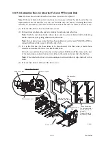
(6)
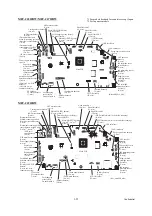
For 100 V series
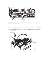
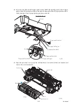
As shown below, unlatch the power cord bush and pull it up from the AC
cord holder. Then release the power cord from the cable guides provided on the AC cord
holder (shown on
).
For 200 V series
Remove screw "j" to release the grounding wire.
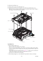
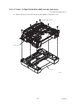
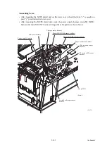
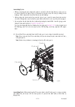
(7) Release the power supply shield from three locks "z" on the lower MJ/PS shield and pull it
up.
(8) Press the latch on the PS PCB insulator and pull out the insulator towards you, while
removing the power cord from the insulator.
(9) Remove three screws "h" from the power supply PCB.
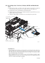
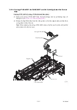
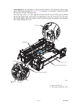
(10)
For 100 V series
Remove screws "e" and "i" and detach the AC cord holder from the
lower MJ/PS shield.
For 200 V series
Remove two screws "e" that secure the power inlet bracket and take the
bracket out together with the power inlet. Release the power cord from the cable guides.
Note:
If the EXT cap has not been removed, remove it beforehand.
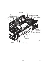
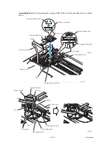
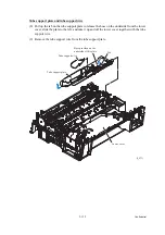
(11) Remove two screws "f" and detach the MJ shield from the lower MJ/PS shield.
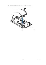
(12) Disconnect the main-MJ (LINE) harness and main-MJ (EXT) harness from the MJ PCB
and release them from the cable guides on the MJ PCB insulator.
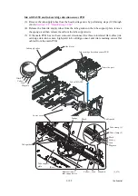
(13) Remove screw "g" and detach the MJ PCB and MJ PCB insulator from the lower MJ/PS
shield.
(3_067)
"e" and "f": Screw, bind M3x4
"g" and "h": Taptite, cup S M3x6
"i": Screw, bind M4x6
"j": Screw pan (washer) M4x8DB
MJ (LINE) harness (yellow)
MJ (EXT) harness (black)
"i"
Power supply shield
Power supply PCB
Lock "x"
"e"
PS PCB insulator
Lock "z"
Lock "z"
Lock "z"
Square opening
Lower MJ/PS frame
MJ PCB insulator
CN2
Cable
guides
AC cord holder
MJ shield
MJ PCB
Power cord
Latch
Latch
CN1
"e"
"f"
"h"
"h"
Earth frame
"j"
"h"
Power cord
bush
MJ shield
"e"
AC cord holder
Power inlet
Power inlet bracket
Grounding wire
"f"
"g"
200 V series
"f"
Summary of Contents for MFC-J6510DW
Page 15: ...xii Confidential ...
Page 16: ...xiii Confidential ...
Page 17: ...xiv Confidential ...
Page 18: ...xv Confidential ...
Page 19: ...xvi Confidential ...
Page 128: ...3 3 Confidential 3 2 PACKING For models with paper tray 2 ...
Page 273: ...4 13 Confidential EXIT Adjust Check Pattern 1 ...
Page 274: ...4 14 Confidential EXIT Adjust Check Pattern 2 ...
Page 275: ...4 15 Confidential EXIT Adjust Check Pattern 3 ...
Page 276: ...4 16 Confidential KEISEN2 LF300 EXIT ADJUST PATTERN ...
Page 278: ...4 18 Confidential KEISEN GAP EXIT ADJUST PATTERN Line 1 Line 2 Line 3 ...
Page 280: ...4 20 Confidential Vertical Alignment Check Patterns ...
Page 283: ...4 23 Confidential Left Right and Bottom Margin Check Pattern ...
Page 286: ...4 26 Confidential Print Pattern for Creating Head Calibration Data ...
Page 302: ...4 42 Confidential ADF Copy Chart C A B D ...
Page 312: ...5 8 Confidential Print Pattern for Creating Head Calibration Data ...
Page 314: ...5 10 Confidential Scanning Compensation Data List ...
Page 317: ...5 13 Confidential Nozzle Test Pattern ...
Page 320: ...5 16 Confidential Configuration List ...
Page 337: ...5 33 Confidential EXIT Adjust Check Pattern 1 ...
Page 338: ...5 34 Confidential EXIT Adjust Check Pattern 2 ...
Page 339: ...5 35 Confidential EXIT Adjust Check Pattern 3 ...
Page 340: ...5 36 Confidential KEISEN2 LF300 EXIT ADJUST PATTERN ...
Page 346: ...5 42 Confidential Vertical Alignment Check Pattern ...
Page 349: ...5 45 Confidential Left Right and Bottom Margin Check Pattern ...
Page 383: ...6 4 Confidential Power supply PCB 100 V series ...
Page 384: ...6 5 Confidential Power supply PCB 200 V series ...
Page 385: ...6 6 Confidential Wiring diagrams ...


