


3-50
Confidential
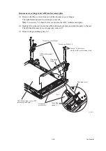
3.9.3 Scanner Cover (Scanner Unit) and Scanner Cover Support
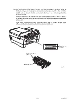
The scanner cover should be removed together with the ADF & document cover ASSY whose
removal procedure is given in
. The disassembly of the ADF & document cover
ASSY is detailed in
.
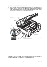
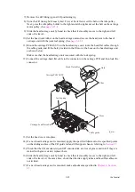
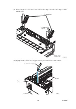
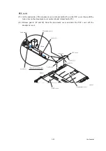
(1) Disconnect the white CIS flat cable (for second side scanning)* from the main PCB and
remove the two flat cores from the cable.
*For duplex scanning models
(2) Disconnect the black CIS flat cable (for first side scanning) from the main PCB and pull it
to the rear through the two flat cores* (single flat core for the simplex scanning models),
and then release it from the cable guides. Unlatch the flat cores and take them out of the
upper cover.
Note
: After disconnecting the flat cable(s), check that each cable is not damaged at its end
or short-circuited. When connecting the flat cable(s), do not insert it at an angle. After
insertion, check again that it is not at an angle.
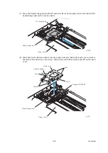
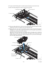
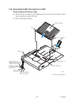
(3) Release the two CIS flat cables from the cable guides together with the flat cable support.
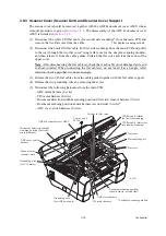
(4) Release the two grounding wires by removing the screw.
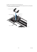
(5) Disconnect the following harnesses from the main PCB.
- ADF motor harness (4-wire)
- CIS motor harness (4-wire)
- Document detection/width & scanning position (first side) sensors harness (7-wire)
- Document scanning position sensor harness (second side) (3-wire)*
- ADF cover switch harness (2-wire)
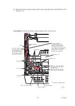
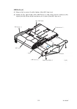
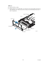
(3_019)
ADF & document cover ASSY
ADF cover switch
harness
Scanner cover
(Scanner unit)
Grounding wire
(for CIS motor)
Grounding wire
(for ADF drive unit)
CIS motor harness
ADF motor harness
Flat cores
Flat cores
Latches for flat cores
Flat cable support
Taptite, cup S
M3x6
* For duplex scanning models
CIS flat cable (white) for
second side scanning*
Document detection/width &
scanning position (first side)
sensors harness
Document scanning position
sensor harness (second side)*
CIS flat cable (black)
for first side scanning
Summary of Contents for MFC-J6510DW
Page 15: ...xii Confidential ...
Page 16: ...xiii Confidential ...
Page 17: ...xiv Confidential ...
Page 18: ...xv Confidential ...
Page 19: ...xvi Confidential ...
Page 128: ...3 3 Confidential 3 2 PACKING For models with paper tray 2 ...
Page 273: ...4 13 Confidential EXIT Adjust Check Pattern 1 ...
Page 274: ...4 14 Confidential EXIT Adjust Check Pattern 2 ...
Page 275: ...4 15 Confidential EXIT Adjust Check Pattern 3 ...
Page 276: ...4 16 Confidential KEISEN2 LF300 EXIT ADJUST PATTERN ...
Page 278: ...4 18 Confidential KEISEN GAP EXIT ADJUST PATTERN Line 1 Line 2 Line 3 ...
Page 280: ...4 20 Confidential Vertical Alignment Check Patterns ...
Page 283: ...4 23 Confidential Left Right and Bottom Margin Check Pattern ...
Page 286: ...4 26 Confidential Print Pattern for Creating Head Calibration Data ...
Page 302: ...4 42 Confidential ADF Copy Chart C A B D ...
Page 312: ...5 8 Confidential Print Pattern for Creating Head Calibration Data ...
Page 314: ...5 10 Confidential Scanning Compensation Data List ...
Page 317: ...5 13 Confidential Nozzle Test Pattern ...
Page 320: ...5 16 Confidential Configuration List ...
Page 337: ...5 33 Confidential EXIT Adjust Check Pattern 1 ...
Page 338: ...5 34 Confidential EXIT Adjust Check Pattern 2 ...
Page 339: ...5 35 Confidential EXIT Adjust Check Pattern 3 ...
Page 340: ...5 36 Confidential KEISEN2 LF300 EXIT ADJUST PATTERN ...
Page 346: ...5 42 Confidential Vertical Alignment Check Pattern ...
Page 349: ...5 45 Confidential Left Right and Bottom Margin Check Pattern ...
Page 383: ...6 4 Confidential Power supply PCB 100 V series ...
Page 384: ...6 5 Confidential Power supply PCB 200 V series ...
Page 385: ...6 6 Confidential Wiring diagrams ...


