


3-49
Confidential
7) Remove the LR fitting jig and LR positioning jig.
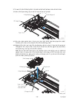
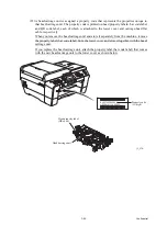
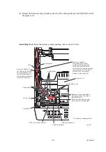
8) Untie the CR timing belt loosely tied. First, at the left end, set the belt on the idle pulley.
Next, press the idle pulley holder to the right and at the right end, set the belt on the carriage
motor pulley. (See
.)
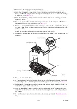
9) Slide the head/carriage unit by hand to check that it smoothly moves to the right and left
ends of its travel.
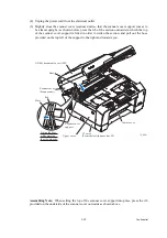
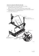
10) Set the head joint rubber on the head/carriage unit and secure the head joint to the head/
carriage unit with the joint leaf spring. (See
.)
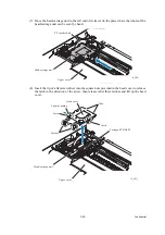
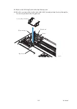
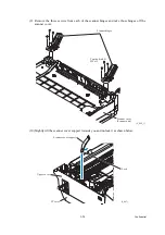
11) Mount the carriage PCB ASSY on the head/carriage unit, route the head flat cables through
the cable guide, and fit the hole provided in the film over the boss on the head/carriage unit
as shown below.
Make sure that the head/carriage unit is secured with the lock spring.
12) Connect the carriage-head flat cable to the connector on the carriage PCB and then lock the
connector.
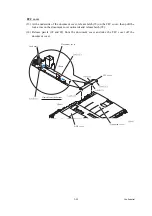
13) Set the head cover into place.
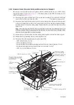
14) If a new head/carriage unit is mounted, apply the specified lubricant to the specified points
on the sliding surface of the CR guide rail and CR support chassis, referring to
.
15) Check that the CR encoder strip and PF encoder disk are free of grease and ink. If they are
stained with grease or ink, replace them.
16) Slide the head/carriage unit by hand to check that it smoothly moves to the right and left
ends of its travel. At the same time, check that the ink supply tubes and head flat cables are
not twisted.
17) If a new head/carriage unit is mounted, make adjustments specified in
(3_016)
Carriage PCB ASSY
Lock spring
Carriage-head flat cable
Cable guide
Boss
Film
Hole
Head flat cables
Summary of Contents for MFC-J6510DW
Page 15: ...xii Confidential ...
Page 16: ...xiii Confidential ...
Page 17: ...xiv Confidential ...
Page 18: ...xv Confidential ...
Page 19: ...xvi Confidential ...
Page 128: ...3 3 Confidential 3 2 PACKING For models with paper tray 2 ...
Page 273: ...4 13 Confidential EXIT Adjust Check Pattern 1 ...
Page 274: ...4 14 Confidential EXIT Adjust Check Pattern 2 ...
Page 275: ...4 15 Confidential EXIT Adjust Check Pattern 3 ...
Page 276: ...4 16 Confidential KEISEN2 LF300 EXIT ADJUST PATTERN ...
Page 278: ...4 18 Confidential KEISEN GAP EXIT ADJUST PATTERN Line 1 Line 2 Line 3 ...
Page 280: ...4 20 Confidential Vertical Alignment Check Patterns ...
Page 283: ...4 23 Confidential Left Right and Bottom Margin Check Pattern ...
Page 286: ...4 26 Confidential Print Pattern for Creating Head Calibration Data ...
Page 302: ...4 42 Confidential ADF Copy Chart C A B D ...
Page 312: ...5 8 Confidential Print Pattern for Creating Head Calibration Data ...
Page 314: ...5 10 Confidential Scanning Compensation Data List ...
Page 317: ...5 13 Confidential Nozzle Test Pattern ...
Page 320: ...5 16 Confidential Configuration List ...
Page 337: ...5 33 Confidential EXIT Adjust Check Pattern 1 ...
Page 338: ...5 34 Confidential EXIT Adjust Check Pattern 2 ...
Page 339: ...5 35 Confidential EXIT Adjust Check Pattern 3 ...
Page 340: ...5 36 Confidential KEISEN2 LF300 EXIT ADJUST PATTERN ...
Page 346: ...5 42 Confidential Vertical Alignment Check Pattern ...
Page 349: ...5 45 Confidential Left Right and Bottom Margin Check Pattern ...
Page 383: ...6 4 Confidential Power supply PCB 100 V series ...
Page 384: ...6 5 Confidential Power supply PCB 200 V series ...
Page 385: ...6 6 Confidential Wiring diagrams ...


