


4-6
4.1.1 Print Head Unit
During disassembly jobs (except when removing the purge unit, carriage rail, or carriage
ASSY), the print head unit and all the four ink cartridges should be kept in place.
NOTE:
To replace the print head unit with a new one, you need to move the carriage to the ink
replacement position by placing the machine in the ink replacement mode. Do not move the
carriage by hand when the power is off.
NOTE:
If you replace the print head unit with a new one, replace also the ink absorber box and
ink cartridges with new ones.
(1) Plug the power cord into a wall socket.
(2) Press the
Ink
key to place the machine in the ink replacement mode.
(3) Press the
2
key to choose "2. REPLACE INK."
(4) Press the
Menu/Set
key.
The carriage automatically moves left to the ink replacement position.
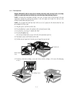
(5) Unplug the power cord from the wall socket.
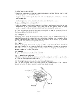
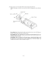
(6) Pull the scanner open lever towards you and open the scanner unit.
Scanner unit
Scanner open
lever
(7) Push the colored ink cartridge covers and remove all ink cartridges. (Or, remove the shipping
cover.)
PUSH
PUSH
PUSH
PUSH
Ink cartridge covers
Summary of Contents for MFC-5100C
Page 1: ...FACSIMILE EQUIPMENT SERVICE MANUAL MODEL MFC5100C MFC590 ...
Page 4: ...CHAPTER 1 GENERAL DESCRIPTION ...
Page 11: ...CHAPTER 2 INSTALLATION ...
Page 19: ...CHAPTER 3 THEORY OF OPERATION ...
Page 39: ...CHAPTER 4 DISASSEMBLY REASSEMBLY LUBRICATION AND ADJUSTMENT ...
Page 114: ...4 73 7 Paper ejection roller gear and PF roller gear 8 Paper feed roller and PF spring ...
Page 116: ...4 75 11 Purge shaft ...
Page 119: ...4 78 Head Positioning Test Pattern ...
Page 120: ...CHAPTER 5 MAINTENANCE MODE ...
Page 127: ...5 6 Scanning Compensation Data List ...
Page 141: ...5 20 Vertical Alignment Check Pattern ...
Page 148: ...CHAPTER 6 ERROR INDICATION AND TROUBLESHOOTING ...
Page 173: ...MFC5100C MFC590 Appendix 1 EEPROM Customizing Codes ...
Page 176: ...MFC5100C MFC590 Appendix 2 Firmware Switches WSW ...
Page 220: ...A Main PCB 1 6 ...
Page 221: ...A Main PCB 2 6 ...
Page 222: ...A Main PCB 3 6 ...
Page 223: ...A Main PCB 4 6 ...
Page 224: ...A Main PCB 5 6 ...
Page 225: ...A Main PCB 6 6 ...
Page 226: ...R27 100 R28 100 R29 100 R30 100 B Relay PCB ...
Page 227: ...C NCU PCB ...
Page 228: ...D Control Panel PCB 1 2 ...
Page 229: ...D Control Panel PCB 2 2 ...
Page 230: ...E Power Supply PCB ...


