


39
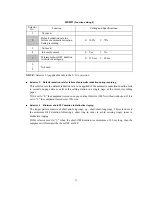
WSW44
(Speeding up scanning-1)
Selector
No.
Function
Setting and Specifications
1
|
5
Not used.
6
|
8
Effective time length of the white
level compensation data obtained
beforehand
No. 6 7 8
0 0 0 : Obtained compensation data
ineffective
0 0 1 :
1 min.
0 1 0 :
3 min.
0 1 1 :
5 min.
1 0 0 :
10 min.
1 0 1 :
15 min.
1 1 0 :
20 min.
1 1 1 :
30 min.
NOTE:
WSW44 is applicable only to models equipped with a flat-bed scanner.
Selectors 6 through 8: Effective time length of the white level compensation data obtained
beforehand
If you set documents in the ADF and the document front sensor detects them or if you open the
document tray ASSY and the document tray open sensor detects the open state, then the controller
will make correction of the reference voltage to be applied to white level compensation for
document scanning before the Copy button is pressed.
These selectors determine how long compensation data obtained beforehand will keep effective.
Summary of Contents for MFC-5100C
Page 1: ...FACSIMILE EQUIPMENT SERVICE MANUAL MODEL MFC5100C MFC590 ...
Page 4: ...CHAPTER 1 GENERAL DESCRIPTION ...
Page 11: ...CHAPTER 2 INSTALLATION ...
Page 19: ...CHAPTER 3 THEORY OF OPERATION ...
Page 39: ...CHAPTER 4 DISASSEMBLY REASSEMBLY LUBRICATION AND ADJUSTMENT ...
Page 114: ...4 73 7 Paper ejection roller gear and PF roller gear 8 Paper feed roller and PF spring ...
Page 116: ...4 75 11 Purge shaft ...
Page 119: ...4 78 Head Positioning Test Pattern ...
Page 120: ...CHAPTER 5 MAINTENANCE MODE ...
Page 127: ...5 6 Scanning Compensation Data List ...
Page 141: ...5 20 Vertical Alignment Check Pattern ...
Page 148: ...CHAPTER 6 ERROR INDICATION AND TROUBLESHOOTING ...
Page 173: ...MFC5100C MFC590 Appendix 1 EEPROM Customizing Codes ...
Page 176: ...MFC5100C MFC590 Appendix 2 Firmware Switches WSW ...
Page 220: ...A Main PCB 1 6 ...
Page 221: ...A Main PCB 2 6 ...
Page 222: ...A Main PCB 3 6 ...
Page 223: ...A Main PCB 4 6 ...
Page 224: ...A Main PCB 5 6 ...
Page 225: ...A Main PCB 6 6 ...
Page 226: ...R27 100 R28 100 R29 100 R30 100 B Relay PCB ...
Page 227: ...C NCU PCB ...
Page 228: ...D Control Panel PCB 1 2 ...
Page 229: ...D Control Panel PCB 2 2 ...
Page 230: ...E Power Supply PCB ...


