


PREFACE
This publication is a Service Manual covering the specifications, construction, theory of operation,
and maintenance of the Brother facsimile equipment. It includes information required for field
troubleshooting and repair--disassembly, reassembly, and lubrication--so that service personnel
will be able to understand equipment function, to rapidly repair the equipment and order any
necessary spare parts.
To perform appropriate maintenance so that the facsimile equipment is always in best condition
for the customer, the service personnel must adequately understand and apply this manual.
This manual is made up of six chapters and appendices.
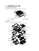
CHAPTER 1
GENERAL DESCRIPTION
CHAPTER 2
INSTALLATION
CHAPTER 3
THEORY OF OPERATION
CHAPTER 4
DISASSEMBLY/REASSEMBLY AND LUBRICATION
CHAPTER 5
MAINTENANCE MODE
CHAPTER 6
ERROR INDICATION AND TROUBLESHOOTING
Appendix 1.
EEPROM Customizing Codes
Appendix 2.
Firmware Switches (WSW)
Appendix 3.
Circuit Diagrams
This manual describes the models and their versions to be destined for major countries. The specifications
and functions are subject to change depending upon each destination.
Summary of Contents for MFC-5100C
Page 1: ...FACSIMILE EQUIPMENT SERVICE MANUAL MODEL MFC5100C MFC590 ...
Page 4: ...CHAPTER 1 GENERAL DESCRIPTION ...
Page 11: ...CHAPTER 2 INSTALLATION ...
Page 19: ...CHAPTER 3 THEORY OF OPERATION ...
Page 39: ...CHAPTER 4 DISASSEMBLY REASSEMBLY LUBRICATION AND ADJUSTMENT ...
Page 114: ...4 73 7 Paper ejection roller gear and PF roller gear 8 Paper feed roller and PF spring ...
Page 116: ...4 75 11 Purge shaft ...
Page 119: ...4 78 Head Positioning Test Pattern ...
Page 120: ...CHAPTER 5 MAINTENANCE MODE ...
Page 127: ...5 6 Scanning Compensation Data List ...
Page 141: ...5 20 Vertical Alignment Check Pattern ...
Page 148: ...CHAPTER 6 ERROR INDICATION AND TROUBLESHOOTING ...
Page 173: ...MFC5100C MFC590 Appendix 1 EEPROM Customizing Codes ...
Page 176: ...MFC5100C MFC590 Appendix 2 Firmware Switches WSW ...
Page 220: ...A Main PCB 1 6 ...
Page 221: ...A Main PCB 2 6 ...
Page 222: ...A Main PCB 3 6 ...
Page 223: ...A Main PCB 4 6 ...
Page 224: ...A Main PCB 5 6 ...
Page 225: ...A Main PCB 6 6 ...
Page 226: ...R27 100 R28 100 R29 100 R30 100 B Relay PCB ...
Page 227: ...C NCU PCB ...
Page 228: ...D Control Panel PCB 1 2 ...
Page 229: ...D Control Panel PCB 2 2 ...
Page 230: ...E Power Supply PCB ...


