


6-13
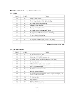
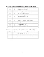
(9) Signal isolation
Code 1
Code 2
Causes
90
01
Unable to detect video signals and commands within 6 seconds
after CFR is transmitted.
90
02
Received PPS containing invalid page count or block count.
(10) Video signal reception
Code 1
Code 2
Causes
A0
03
Error correction sequence not terminated even at the final
transmission speed for fallback.
A0
11
Receive buffer empty. (5-second time-out)
A0
12
Receive buffer full during operation except receiving into
memory.
A0
13
Decoding error continued on 500 lines.
A0
14
Decoding error continued for 10 seconds.
A0
15
Time-out: 5 seconds or more for one-line transmission.
A0
16
RTC not found and carrier OFF signal detected for 6 seconds.
A0
17
RTC found but no command detected for 60 seconds.
A0
18
Receive buffer full during receiving into memory.
A0
19
No video data to be sent
A0
20
Unable to continue to receive color FAX (Remaining ink
insufficient)
A8
01
RTN, PIN, or ERR received at the calling terminal.*
A9
01
RTN, PIN, or ERR received at the called terminal.*
* Available in German versions only
Summary of Contents for MFC-5100C
Page 1: ...FACSIMILE EQUIPMENT SERVICE MANUAL MODEL MFC5100C MFC590 ...
Page 4: ...CHAPTER 1 GENERAL DESCRIPTION ...
Page 11: ...CHAPTER 2 INSTALLATION ...
Page 19: ...CHAPTER 3 THEORY OF OPERATION ...
Page 39: ...CHAPTER 4 DISASSEMBLY REASSEMBLY LUBRICATION AND ADJUSTMENT ...
Page 114: ...4 73 7 Paper ejection roller gear and PF roller gear 8 Paper feed roller and PF spring ...
Page 116: ...4 75 11 Purge shaft ...
Page 119: ...4 78 Head Positioning Test Pattern ...
Page 120: ...CHAPTER 5 MAINTENANCE MODE ...
Page 127: ...5 6 Scanning Compensation Data List ...
Page 141: ...5 20 Vertical Alignment Check Pattern ...
Page 148: ...CHAPTER 6 ERROR INDICATION AND TROUBLESHOOTING ...
Page 173: ...MFC5100C MFC590 Appendix 1 EEPROM Customizing Codes ...
Page 176: ...MFC5100C MFC590 Appendix 2 Firmware Switches WSW ...
Page 220: ...A Main PCB 1 6 ...
Page 221: ...A Main PCB 2 6 ...
Page 222: ...A Main PCB 3 6 ...
Page 223: ...A Main PCB 4 6 ...
Page 224: ...A Main PCB 5 6 ...
Page 225: ...A Main PCB 6 6 ...
Page 226: ...R27 100 R28 100 R29 100 R30 100 B Relay PCB ...
Page 227: ...C NCU PCB ...
Page 228: ...D Control Panel PCB 1 2 ...
Page 229: ...D Control Panel PCB 2 2 ...
Page 230: ...E Power Supply PCB ...


