


5-11
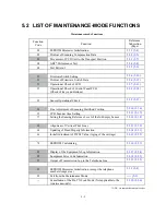
Firmware Switches (WSW01 through WSW50)
Continued
WSW No.
Function
WSW34
Function setting 12
WSW35
Not used.
WSW36
Function setting 14
WSW37
Function setting 15
WSW38
Not used.
WSW39
Not used.
WSW40
Not used.
WSW41
CCD fluorescent lamp
WSW42
Function setting 20
WSW43
Function setting 21
WSW44
Speeding up scanning-1
WSW45
Speeding up scanning-2
WSW46
Monitor of power ON/OFF state and parallel port kept at high
WSW47
Paper handling for a feed error and delay of FAX line disconnection
WSW48
Not used.
WSW49
Not used.
WSW50
Not used.
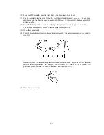
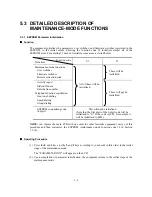
Operating Procedure
(1) Press the
1
and
0
keys in this order in the initial stage of the maintenance mode.
The equipment displays the "WSW00" on the LCD and becomes ready to accept a firmware
switch number.
(2) Enter the desired number from the firmware switch numbers (01 through 50).
The following appears on the LCD:
Selector 1
Selector 8
↓
↓
WSWXX = 0 0 0 0 0 0 0 0
(3) Use the right and left arrow keys to move the cursor to the selector position to be modified.
(4) Enter the desired number using the
0
and
1
keys.
(5) Press the
Set
key. This operation saves the newly entered selector values onto the EEPROM
and readies the equipment for accepting a firmware switch number.
(6) Repeat steps (2) through (5) until the modification for the desired firmware switches is
completed.
(7) Press the
Set
or
Stop
key to return the equipment to the initial stage of the maintenance mode.
NOTES:
• To cancel this operation and return the equipment to the initial stage of the
maintenance mode during the above procedure, press the
Stop
key.
• If there is a pause of more than one minute after a single-digit number is entered for
double-digit firmware switch numbers, the equipment will automatically return to the
initial stage of the maintenance mode.
Details of Firmware Switches
The details of the firmware switches are described in Appendix 2 in which the user-accessible
selectors of the firmware switches are shaded.
Summary of Contents for MFC-5100C
Page 1: ...FACSIMILE EQUIPMENT SERVICE MANUAL MODEL MFC5100C MFC590 ...
Page 4: ...CHAPTER 1 GENERAL DESCRIPTION ...
Page 11: ...CHAPTER 2 INSTALLATION ...
Page 19: ...CHAPTER 3 THEORY OF OPERATION ...
Page 39: ...CHAPTER 4 DISASSEMBLY REASSEMBLY LUBRICATION AND ADJUSTMENT ...
Page 114: ...4 73 7 Paper ejection roller gear and PF roller gear 8 Paper feed roller and PF spring ...
Page 116: ...4 75 11 Purge shaft ...
Page 119: ...4 78 Head Positioning Test Pattern ...
Page 120: ...CHAPTER 5 MAINTENANCE MODE ...
Page 127: ...5 6 Scanning Compensation Data List ...
Page 141: ...5 20 Vertical Alignment Check Pattern ...
Page 148: ...CHAPTER 6 ERROR INDICATION AND TROUBLESHOOTING ...
Page 173: ...MFC5100C MFC590 Appendix 1 EEPROM Customizing Codes ...
Page 176: ...MFC5100C MFC590 Appendix 2 Firmware Switches WSW ...
Page 220: ...A Main PCB 1 6 ...
Page 221: ...A Main PCB 2 6 ...
Page 222: ...A Main PCB 3 6 ...
Page 223: ...A Main PCB 4 6 ...
Page 224: ...A Main PCB 5 6 ...
Page 225: ...A Main PCB 6 6 ...
Page 226: ...R27 100 R28 100 R29 100 R30 100 B Relay PCB ...
Page 227: ...C NCU PCB ...
Page 228: ...D Control Panel PCB 1 2 ...
Page 229: ...D Control Panel PCB 2 2 ...
Page 230: ...E Power Supply PCB ...


