


13
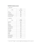
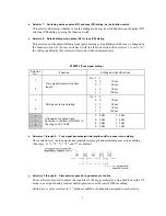
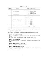
WSW10
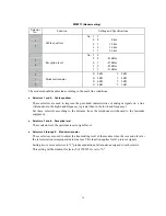
(Protocol definition 2)
Selector
No.
Function
Setting and Specifications
1
Not used.
2
Time length from transmission
of the last dial digit to CML
ON
0: 100 ms
1: 50 ms
3
Time length from CML ON to
CNG transmission
0: 2 sec.
1: 4 sec.
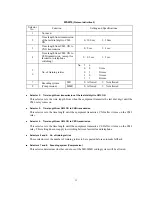
4
Time length from CML ON to
CED transmission (except for
facsimile-to-telephone
switching)
0: 0.5 sec.
1: 2 sec.
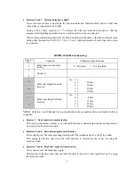
5
6
No. of training retries
No. 5
6
0
0
:
1 time
0
1
:
2 times
1
0
:
3 times
1
1
:
4 times
7
MR
0: Allowed
1: Not allowed
8
Encoding system
(Compression)
MMR
0: Allowed
1: Not allowed
Selector 2:
Time length from transmission of the last dial digit to CML ON
This selector sets the time length from when the equipment transmits the last dial digit until the
CML relay comes on.
Selector 3:
Time length from CML ON to CNG transmission
This selector sets the time length until the equipment transmits a CNG after it turns on the CML
relay.
Selector 4:
Time length from CML ON to CED transmission
This selector sets the time length until the equipment transmits a CED after it turns on the CML
relay. This setting does not apply to switching between facsimile and telephone.
Selectors 5 and 6: No. of training retries
These selectors set the number of training retries to be repeated before automatic fallback.
Selectors 7 and 8: Encoding system (Compression)
This selector determines whether or not use of the MR/MMR coding system will be allowed.
Summary of Contents for MFC-5100C
Page 1: ...FACSIMILE EQUIPMENT SERVICE MANUAL MODEL MFC5100C MFC590 ...
Page 4: ...CHAPTER 1 GENERAL DESCRIPTION ...
Page 11: ...CHAPTER 2 INSTALLATION ...
Page 19: ...CHAPTER 3 THEORY OF OPERATION ...
Page 39: ...CHAPTER 4 DISASSEMBLY REASSEMBLY LUBRICATION AND ADJUSTMENT ...
Page 114: ...4 73 7 Paper ejection roller gear and PF roller gear 8 Paper feed roller and PF spring ...
Page 116: ...4 75 11 Purge shaft ...
Page 119: ...4 78 Head Positioning Test Pattern ...
Page 120: ...CHAPTER 5 MAINTENANCE MODE ...
Page 127: ...5 6 Scanning Compensation Data List ...
Page 141: ...5 20 Vertical Alignment Check Pattern ...
Page 148: ...CHAPTER 6 ERROR INDICATION AND TROUBLESHOOTING ...
Page 173: ...MFC5100C MFC590 Appendix 1 EEPROM Customizing Codes ...
Page 176: ...MFC5100C MFC590 Appendix 2 Firmware Switches WSW ...
Page 220: ...A Main PCB 1 6 ...
Page 221: ...A Main PCB 2 6 ...
Page 222: ...A Main PCB 3 6 ...
Page 223: ...A Main PCB 4 6 ...
Page 224: ...A Main PCB 5 6 ...
Page 225: ...A Main PCB 6 6 ...
Page 226: ...R27 100 R28 100 R29 100 R30 100 B Relay PCB ...
Page 227: ...C NCU PCB ...
Page 228: ...D Control Panel PCB 1 2 ...
Page 229: ...D Control Panel PCB 2 2 ...
Page 230: ...E Power Supply PCB ...


