


6-21
Trouble
Action to be taken
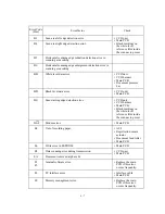
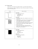
(7)
Print edges not aligned
At the printer
• Check the alignment of vertical print lines by using the
maintenance-mode function code 65. (Refer to CHAPTER 5,
Subsection 5.3.13).
• Check the print head unit.
• Check the encoder strip for stains or scratches. (If the
encoder strip is not hooked properly, correct it.)
(8)
Ink splash
At the printer
• For each of the four ink-jet units, perform the head purging
operation several times to remove dust or air bubbles from its
nozzles.
• Check the ink cartridges. Any of them has run out of ink or
the ink viscosity has been increased, so replace it.
• Replace the print head unit.
• Replace the main PCB.
• Replace the power supply PCB.
• Check that the eccentric bushings R and L are aligned with
markings made on the main chassis to adjust the head-platen
gap.
(9)
Random missing dots
At the printer
• For each of the four ink-jet units, perform the head purging
operation several times to remove dust or air bubbles from its
nozzles.
• Check the ink cartridges. If any cartridges have run out of ink,
replace them.
• Check the dimple contact between each of the print head PCB
and the mating carriage PCB. Clean it if contaminated.
• Replace the print head unit.
(If the problem persists, replace the carriage ASSY.)
• Check the connection of the head flat cables on the main PCB.
(If either of those cables is broken or damaged, replace it.)
• Replace the main PCB.
• Clean the head caps and wiper of the purge unit with a
Rubycel stick. For the cleaning procedure, refer to "Cleaning
the purge unit" given on page 6-23.
Summary of Contents for MFC-5100C
Page 1: ...FACSIMILE EQUIPMENT SERVICE MANUAL MODEL MFC5100C MFC590 ...
Page 4: ...CHAPTER 1 GENERAL DESCRIPTION ...
Page 11: ...CHAPTER 2 INSTALLATION ...
Page 19: ...CHAPTER 3 THEORY OF OPERATION ...
Page 39: ...CHAPTER 4 DISASSEMBLY REASSEMBLY LUBRICATION AND ADJUSTMENT ...
Page 114: ...4 73 7 Paper ejection roller gear and PF roller gear 8 Paper feed roller and PF spring ...
Page 116: ...4 75 11 Purge shaft ...
Page 119: ...4 78 Head Positioning Test Pattern ...
Page 120: ...CHAPTER 5 MAINTENANCE MODE ...
Page 127: ...5 6 Scanning Compensation Data List ...
Page 141: ...5 20 Vertical Alignment Check Pattern ...
Page 148: ...CHAPTER 6 ERROR INDICATION AND TROUBLESHOOTING ...
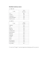
Page 173: ...MFC5100C MFC590 Appendix 1 EEPROM Customizing Codes ...
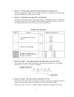
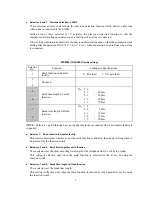
Page 176: ...MFC5100C MFC590 Appendix 2 Firmware Switches WSW ...
Page 220: ...A Main PCB 1 6 ...
Page 221: ...A Main PCB 2 6 ...
Page 222: ...A Main PCB 3 6 ...
Page 223: ...A Main PCB 4 6 ...
Page 224: ...A Main PCB 5 6 ...
Page 225: ...A Main PCB 6 6 ...
Page 226: ...R27 100 R28 100 R29 100 R30 100 B Relay PCB ...
Page 227: ...C NCU PCB ...
Page 228: ...D Control Panel PCB 1 2 ...
Page 229: ...D Control Panel PCB 2 2 ...
Page 230: ...E Power Supply PCB ...


