Brother HL 2030 Service Manual Download Page 181

HL-2030/2040/2070N SERVICE MANUAL 

Confidential 

7-17

5.    SOFTWARE SETTING PROBLEMS 

The printer may not print the data correctly if there are incorrect software settings.   


S-1 

“There was an error writing to LPT1: (or BRUSB) for the printer” error message 
appears. 


User Check 

(1)  Check that the printer cable is not damaged or broken.  Check also that the cable is connected 

to the correct interface connectors of both the printer and PC. 

(2)  Check that the correct printer is selected if you have an interface switching device. 

(3)  Check that the appropriate printer driver is selected as ‘Set as Default’.  Check also that the 

correct print port is set for the selected printer driver. 

(4)  Check that the printer is not connected to the same port which is also connected to a mass 

storage device or scanner.  Remove all other devices and connect the port to the printer only.  
Turn off the printer status monitor in the device options tab in the printer driver. 

(5)  If the print port is set as an ECP port, change it to a normal port. 

(6)  Try printing the test page refer to

 ‘Test Sample Page’ in Chapter 8.


(7)  Try resetting the factory settings. 
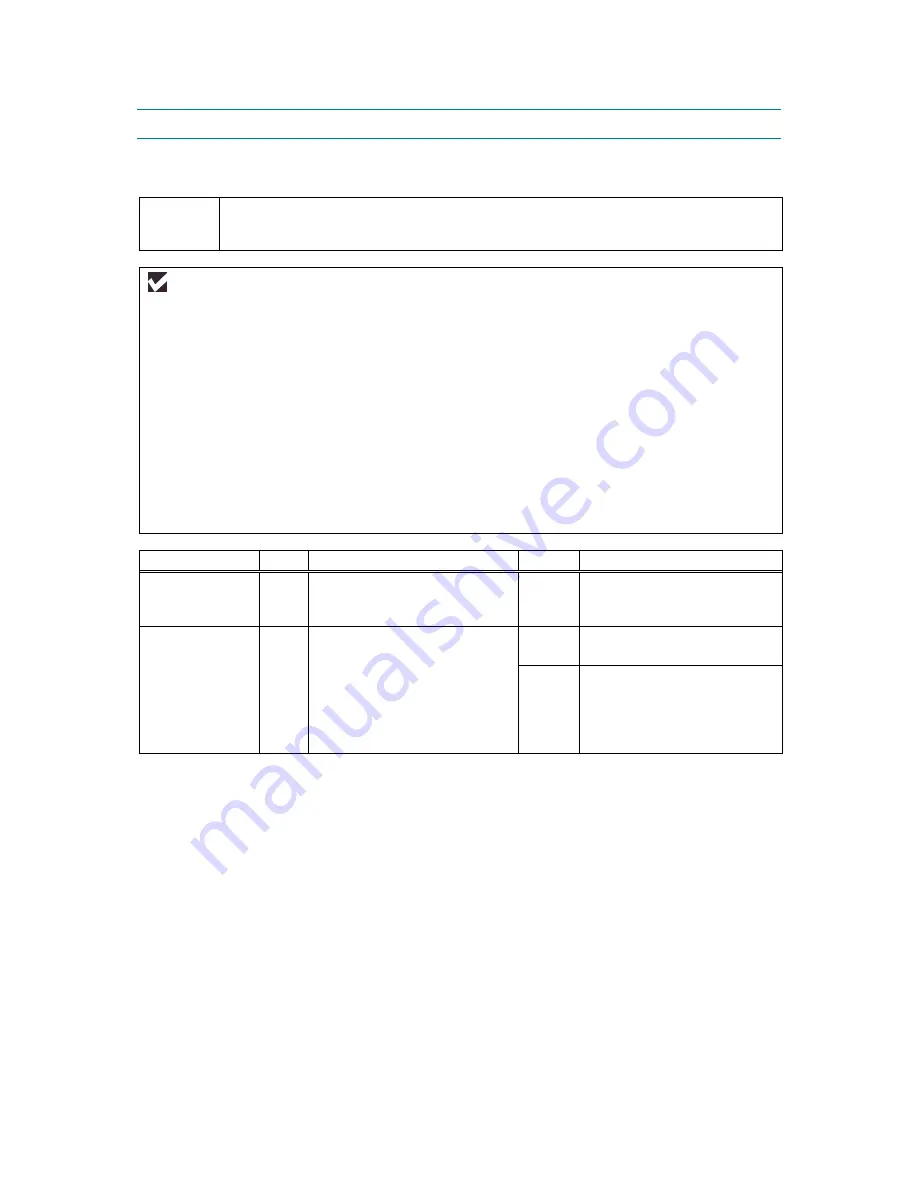
 

Possible cause 

Step

Check 

Result

Remedy


Failure inside 
the printer  

Is it possible to print the test 
page with the method of 

‘Test 

Sample Page’ in Chapter 8.? 


No 

Identify the error type, then 
refer to the specified section 
of this chapter. 

Main PCB 
failure 

Is it possible to print with 
another PC and printer cable? 

No 

Replace the main PCB. 


Yes 

This problem may appear 
under the specified system 
environment.  Check the 
environment which the user 
used. 


Summary of Contents for HL 2030

Page 1: ...other Laser Printer SERVICE MANUAL MODEL HL 2030 2040 2070N Read this manual thoroughly before maintenance work Keep this manual in a convenient place for quick and easy reference at all times November 2004 SM PRN054 ...

Page 2: ...mark and FX 80 and FX 850 are trademarks of Seiko Epson Corporation Hewlett Packard is a registered trademark and HP LaserJet 6P 6L 5P 5L 4 4L 4P III IIIP II and IIP are trademarks of Hewlett Packard Company IBM IBM PC and Proprinter are registered trademarks of International Business Machines Corporation Microsoft MS DOS Windows and Windows NT are registered trademarks of Microsoft Corporation in...

Page 3: ...SASSEMBLY AND RE ASSEMBLY Procedures for disassembling and re assembling the mechanical system CHAPTER 5 PERIODIC MAINTENANCE Periodical replacement parts consumable parts etc CHAPTER 6 ADJUSTMENTS AND UPDATING OF SETTING REQUIRED AFTER PARTS REPLACEMENT CHAPTER 7 TROUBLESHOOTING Reference values and adjustments troubleshooting image defects troubleshooting malfunctions etc CHAPTER 8 SERVICE SUPPO...

Page 4: ...9 Toner Cartridge Weight Information 1 17 4 SERIAL NO DESCRIPTIONS 1 18 CHAPTER 2 INSTALLATION AND BASIC OPERATION 2 1 1 CONDITIONS REQUIRED FOR INSTALLATION 2 1 1 1 Power Supply 2 1 1 2 Environment 2 1 1 3 System Requirements for Brother Printer Solution 2 2 2 UNPACKING 2 3 3 INSTALL THE PRINTER 2 4 3 1 For All Users 2 4 3 1 1 Install the drum unit assembly 2 5 3 1 2 Load paper in the paper tray ...

Page 5: ...Functions 2 27 6 2 Network Factory Default Setting For HL 2070N 2 27 6 3 Network Factory Default Setting with APIPA Protocol Disabled For HL 2070N 2 28 7 OPTIONAL PRINT SERVER 2 29 CHAPTER 3 THEORY OF OPERATION 3 1 1 ELECTRONICS 3 1 1 1 General Block Diagram 3 1 1 2 Main PCB Block Diagram 3 2 1 3 Main PCB 3 3 1 3 1 CPU 3 3 1 3 2 USB interface 3 5 1 3 3 IEEE 1284 interface 3 6 1 3 4 Network interfa...

Page 6: ...OCEDURE 4 3 3 1 AC Cord 4 3 3 2 Drum Tone ASSY 4 3 3 3 Paper Tray 4 4 3 4 Rear Cover 4 5 3 5 Rear Chute Cover 4 6 3 6 Side Cover L 4 7 3 7 Side Cover R 4 7 3 8 Top Cover Paper Stopper 4 8 3 9 Front Cover 4 10 3 10 Pickup Roller Holder ASSY 4 11 3 11 Fixing Unit 4 15 3 12 High Voltage PS PCB ASSY 4 21 3 13 Main PCB 4 22 3 14 SW Key Panel PCB 4 24 3 15 PS PCB Unit 4 25 3 16 Laser Unit 4 28 3 17 Sub ...

Page 7: ...RTS 5 9 3 PERIODICAL CLEANING 5 10 3 1 Cleaning the Inside of the Printer 5 10 3 2 Cleaning the Corona Wire 5 10 3 3 Cleaning the Scanner Window 5 11 3 4 Cleaning the Electrical Terminals 5 12 CHAPTER 6 ADJUSTMENTS AND UPDATING OF SETTINGS REQUIRED AFTER PARTS REPLACEMENT 6 1 1 IF YOU REPLACE THE MAIN PCB 6 1 CHAPTER 7 TROUBLESHOOTING 7 1 1 INTRODUCTION 7 1 1 1 Initial Check 7 1 1 2 Warnings for M...

Page 8: ... 8 1 1 1 User Mode 8 1 1 2 User Maintenance Mode 8 3 1 3 Service Mode 8 4 2 HOW TO USE THE SELF DIAGNOSTICS TOOLS 8 12 2 1 Diagnostics 8 12 2 2 Printer Information 8 14 3 NVRAM DEFAULT VALUE 8 15 APPENDICES 1 MAIN PCB CIRCUIT DIAGRAM HL 2030 2040 1 3 A 1 2 MAIN PCB CIRCUIT DIAGRAM HL 2030 2040 2 3 A 2 3 MAIN PCB CIRCUIT DIAGRAM HL 2030 2040 3 3 A 3 4 MAIN PCB CIRCUIT DIAGRAM HL 2070N 1 3 A 4 5 MAI...

Page 9: ...roducts marketed in the United States One of the following labels on the back of the printer indicates compliance with the FDA regulations and must be attached to laser products marketed in the United States The label for Japanese manufactured products MANUFACTURED Brother Industries Ltd 15 1 Naeshiro cho Mizuho ku Nagoya 467 8561 Japan This product complies with FDA performance standards for lase...

Page 10: ...he standards never touch it Caution Use of controls adjustments or performance of procedures other than those specified in this manual may result in hazardous radiation exposure For Finland and Sweden LUOKAN 1 LASERLAITE KLASS 1 LASER APPARAT Varoitus Laitteen käyttäminen muulla kuin tässä käyttöohjeessa mainitulla tavalla saattaa altistaa käyttäjän turvallisuusluokan 1 ylittävälle näkymättömälle ...

Page 11: ...of the laser unit ACHTUNG Im Falle von Störungen der Lasereinheit muß diese ersetzt werden Das Gehäuse der Lasereinheit darf nicht geöffnet werden da sonst Laserstrahlen austreten können Location of the laser beam window ADDITIONAL INFORMATION When servicing the optical system of the printer be careful not to place a screwdriver or other reflective object in the path of the laser beam Be sure to t...

Page 12: ...rious kinds of WARNING messages included in this manual WARNING Always turn off the power switch and unplug the power cord from the power outlet before accessing any parts inside the printer WARNING Some parts inside the printer are extremely hot immediately after the printer is used When opening the front cover or back cover to access any parts inside the printer never touch the shaded parts show...

Page 13: ...nt resolution water mark and many layout functions You can easily setup these print options through the Printer Setup Menu Printer Status Monitor with Bi directional Parallel Interface For HL 2040 2070N The printer driver can monitor the status of your printer using bi directional parallel communications IEEE 1284 bi directional parallel printer cable is recommended The printer status monitor prog...

Page 14: ...rtain period of time The printer consumes less than 5W HL 2030 2040 or 7W HL 2070N when in sleep mode Low Running Cost Since the toner cartridge is separate from the drum unit you need to replace only the toner cartridge after printing around 2 500 Standard toner cartridge pages at 5 coverage for A4 paper for the standard cartridge which is both cost effective and ecologically friendly Bar Code Pr...

Page 15: ... based on HL 2070N Fig 1 2 Power Switch Front Cover Paper Tray Manual Feed Paper Guides Manual Feed Slot Face down Output Tray Support Flap Support Flap Control Panel Face down Output Tray LED Light emitting Diode HL 2070N Side cover USB Interface Connector 10 100Baser TX Port HL 2070N Parallel Interface Connector HL 2040 and HL 2070N AC Power Connector Back Cover ...

Page 16: ...30 Up to 16 pages minute A4 Up to 17 pages minute Letter size paper HL 2040 HL 2070N Up to 20 pages minute A4 Up to 20 pages minute Letter size paper Warm up Max 18 seconds at 23 C 73 4 F First print Less than 10 seconds when the printer is in the ready state when loading A4 or Letter size paper from the standard paper tray Consumables Toner cartridge Life expectancy Starter 1 500 pages cartridge ...

Page 17: ...r Driver for Mac OS 9 1 to 9 2 and Mac OS X 10 2 4 or greater GDI Printer Driver for Linux Interface Standard HL 2030 HL 2040 HL 2070N Full Speed USB 2 0 Full Speed USB 2 0 IEEE 1284 Parallel Full Speed USB 2 0 IEEE 1284 Parallel 10 100 BASE TX Option HL 2030 HL 2040 HL 2070N IEEE 802 11b wireless NC 2200w IEEE 802 11b wireless NC 2200w 10 100 BASE TX NC 2100p IEEE 802 11b wireless NC 2200w Utilit...

Page 18: ...A is not suitable for operation in rooms where predominantly intellectual work is done Due to there noise emissions these devices should be separate rooms Standing by 4 3B A Temperature Operating 10 to 32 5 C 50 to 90 5 F Non operating 0 to 40 C 38 to 104 F Storage 20 to 40 C 4 to 104 F Humidity Operating 20 to 80 non condensing Storage 10 to 85 non condensing Dimensions 371 x 361 x 165 5 mm W x D...

Page 19: ...maintain the product Machine Life 50 000 pages 5 years MTBF Meantime between failure Up to 4 000 hours MTTR Meantime to repair Average 30 minutes Monthly volume 10 000 pages Periodical replacement parts There is no periodical replacement part that needs to be replaced periodically to maintain the product quality ...

Page 20: ...ent SMB Print IPP FTP Server mDNS TELNET SNMP HTTP Management Tool Web Based Management HTTPD BRAdmin Professional Web BRAdmin Supplied software BRAdmin Professional utility for Windows 95 98 ME Windows NT 4 0 Windows 2000 XP Web BRAdmin Windows 2000 Professional Server Advanced Server Windows XP Professional Web BRAdmin is NOT supplied with CD ROM Available only on Web page For more information o...

Page 21: ...er 105 g m 2 to 161 g m 2 28 to 43 lbs X O Thick paper or Thicker paper Transparency O Up to 10 sheets A4 or Letter O A4 or Letter Transparency Label X O A4 or Letter Thicker paper Envelop X O Envelope or Env Thick or Env Thin Card Stock X O Thick paper or Thicker paper 2 Paper size Paper Tray Manual feed slot Paper size A4 Letter Legal B5 ISO Executive A5 A6 B6 ISO B5 JIS Folio Width 69 9 to 215 ...

Page 22: ...formation given below to prevent any paper jams print quality problems or printer damage It is recommended to use long grained paper for the best print quality If short grained paper is being used it might be the cause of paper jams Use neutral paper Do not use acid paper to avoid any damage to the drum unit Avoid using coated paper such as vinyl coated paper Avoid using preprinted or highly textu...

Page 23: ...r tray capacity Paper Tray Manual feed slot Paper Capacity 250 sheets 80 g m 2 or 21lb Single sheet 3 6 3 Print delivery Face down output tray capacity Maximum 100 sheets 80 g m 2 face down only Note Face down Delivery with the printed face of the paper downwards ...

Page 24: ...A B C D E F G F G E G G Physical page Printable area Logical page B Physical page length D Maximum logical page length F Distance from edge of physical page to edge of logical page NOTE Logical page shows the printable area for a PCL driver Printable area shows mechanical printable area of the machine Therefore the machine can only print within the shaded area when you use a PCL driver ...

Page 25: ...ots Ç 0 mm 4 2 mm 0 16 50 dots B 5 JIS 182 0 mm 7 1 2 130 dots 257 0 mm 10 11 3 033 dots 170 0 mm 6 69 2 007 dots 257 0 mm 10 11 3 033 dots Ç 0 mm 4 2 mm 0 16 50 dots B 5 ISO 176 0 mm 6 93 2 078 dots 250 0 mm 9 84 2 952 dots 164 0 mm 6 46 1 936 dots 250 0 mm 9 84 2 952 dots Ç 0 mm 4 2 mm 0 16 50 dots B 6 ISO 125 0 mm 4 92 1 476 dots 176 0 mm 6 93 2 078 dots 164 0 mm 4 44 1 334 dots 176 0 mm 6 93 2...

Page 26: ...ysical page length D Maximum logical page length F Distance from edge of physical page to edge of logical page NOTE Logical page shows the printable area for a PCL driver Printable area shows mechanical printable area of the machine Therefore the machine can only print within the shaded area when you use a PCL driver ...

Page 27: ...m 10 11 3 033 dots 182 0 mm 7 1 2 130 dots 247 0 mm 9 72 2 916 dots 182 0 mm 7 1 2 130 dots Ç 0 mm 4 2 mm 0 16 50 dots B 5 ISO 250 0 mm 9 84 2 952 dots 176 0 mm 6 93 2 078 dots 240 0 mm 9 44 2 834 dots 176 0 mm 6 93 2 078 dots Ç 0 mm 4 2 mm 0 16 50 dots B 6 ISO 176 0 mm 6 93 2 078 dots 125 0 mm 4 92 1 476 dots 166 4 mm 6 55 1 960 dots 125 0 mm 4 92 1 476 dots Ç 0 mm 4 2 mm 0 16 50 dots COM10 241 3...

Page 28: ...els Transparency Up to 16 17 ppm HL 2030 Up to 20 ppm HL 2040 2070N Thin Paper Up to 16 17 ppm HL 2030 Up to 20 ppm HL 2040 2070N Plain Paper Recycled Paper 300sec 16 17 ppm Æ 8 ppm HL 2030 300sec 20 ppm Æ 8 ppm HL 2040 2070N Env Thin 300sec 10 ppm Æ 8 ppm HL 2030 300sec 10 ppm Æ 8 ppm HL 2040 2070N Thick Paper Envelopes 30sec 10 ppm Æ 8 ppm HL 2030 30sec 10 ppm Æ 8 ppm HL 2040 2070N Thicker Bond ...

Page 29: ...Weight at Toner Life End 44g 44g You can print 500 pages 100 pages with 10g toner 5 coverage NOTE Without yellow protector Toner cartridge weight may vary within 2 to 3g depending on the cartridge weight The weight of the starter toner cartridge is as follows For TN2000 model the starter toner cartridge weight is 610g and the toner weight is 80g For TN350 TN2050 and TN2025 models the starter toner...

Page 30: ...ya Plant A Mie Brother C BIUK J Buji Nan Ling Factory 1 Printer Printed on the label attached on the rear of the main body Example U 5 2 6 8 2 A 3 J 1 1 1 1 0 1 2 Process unit Imprinted on the aluminum bag Drum unit with toner cartridge 3 A 1 1 J A 3 Drum unit Printed on the bar code label attached inside the drum unit A 3 J 5 1 0 0 1 0 4 A MODEL NO MONTH SERIAL NO DR TN REUSE The first time M The...

Page 31: ...CTION INFO DR TN REUSE The first time M The second time N The third time P POLYGON MOTOR DISTINCTION 1 SHINANO KENSHI CO LTD 2 MATSUSHITA ELECTRIC INDUSTRIAL CO 3 JVC 4 SAMSUNG INSPECTION MACHINE SERIAL NUMBER OF INSPECTION MACHINE ADJUSTED VALUE YEAR MONTH DATE FACTORY ID NO PRODUCTION LINE NO MONTH YEAR FACTORY ID NO TONER VOLUME L 80g M 100g SERIAL NO PRODUCTION LINE NO LSU MODEL DISTINCTION FR...

Page 32: ...re is maintained between 10 C and 32 5 C The relative humidity is maintained between 20 and 80 The printer should be used in a well ventilated room Place the printer on a flat horizontal surface Keep the printer clean Do not place the printer in a dusty place Do not place the printer where the ventilation hole of the printer is blocked Keep approximately 100 mm 4 inches between the ventilation hol...

Page 33: ... System Operating System Version Processor Speed Minimum RAM Recommended RAM Available Hard Disk Space 95 98 98SE 486 66MHz 8MB 16MB 40MB NT Workstation 4 0 Pentium 75MHz 16MB 32MB 50MB 2000 Professional Pentium 133MHz 64MB 128MD 50MB Me Pentium 150MHz 32MB 64MB 50MB Windows XP Pentium 300MHz 128MB 128MB 50MB OS 9 1 to 9 2 32MB 64MB Apple OS X 10 2 4 or greater All base models meet minimum system ...

Page 34: ... is not available for HL 2030 Do not use a Parallel interface cable that is longer than 6 feet 2 meters USB cable For Windows 98 Me 2000 XP Mac OS 9 1 9 2 Mac OS X 10 2 4 or greater users only Please make sure that you use a Hi Speed USB 2 0 certified cable if your computer uses a Hi Speed USB 2 0 interface Do not connect the USB cable to a non powered hub or a Mac keyboard Please make sure that y...

Page 35: ...rams for the hardware setup and driver installation are contained on the supplied CD ROM 3 1 For All Users For Windows users 1 Turn on the PC power Insert the supplied CD ROM into the CD ROM drive The opening screen will appear automatically Select the printer model and the language 2 Click the Initial Setup icon on the menu screen 3 You can view the Initial Setup instructions For Mac OS 10 2 4 or...

Page 36: ...mbly in the printer Fig 2 2 5 Close the front cover of the printer 3 1 2 Load paper in the paper tray 1 Pull the paper tray completely out of the printer 2 While pressing the paper guide release lever slide the adjusters to fit the paper size Check that the guides are firmly in the slots Fig 2 3 NOTE For Legal size paper pull out the back of the paper tray while holding the inside latch of the tra...

Page 37: ... paper tray at one time When you use pre printed paper put the side that is going to be printed on blank side face down with the top of the paper at the front of the tray 5 Put the paper tray firmly back in the printer Check that it is completely in the printer 3 1 3 Print a test page 1 Turn off the printer 2 Make sure that the front cover is closed and the AC power cord is plugged in 3 All LEDs l...

Page 38: ...Read the license agreement carefully Follow the on screen instructions 4 When this screen appears make sure the printer power switch is on Connect the USB interface cable to your PC and then connect it to the printer Click the Next button Fig 2 6 6 Click the Finish button For Windows 98 Me users The setup is now complete For Windows 2000 XP users Follow the instructions below for setting the PC as...

Page 39: ...Follow the on screen instructions 2 Click the Install Other Drivers or Utilities icon on the menu screen 3 Click BRAdmin Professional Follow the instructions on the screen NOTE The default password for the print server is access You can use the BRAdmin Professional software or a web browser to change this password Please use the BRAdmin Professional utility version that was supplied on the CD ROM ...

Page 40: ...eer to Peer Network Printer and then click the Next button 8 Follow the instructions below depending on it For Network shared printer users Go to 3 For Network shared printer users For LPR users Go to 4 For Brother Peer to Peer network printer users LPR recommended Peer to Peer printing method For NetBIOS users Go to 5 For Brother Peer to Peer network printer users NetBIOS 3 For Network shared pri...

Page 41: ...ick the Next button Fig 2 9 3 Click the Finish button For WindowsNT 4 0 and Windows 2000 XP users The setup is now complete For Windows 95 98 ME users After your PC has restarted the setup will be complete 5 For Brother Peer to Peer network printer users NetBIOS Configuring the NetBIOS port 1 Select Search the network for devices and choose from a list of discovered devices Recommended and then cl...

Page 42: ...es folder 7 Open the Printer Setup Utility icon 8 Click Add And select USB 9 Select the appropriate printer and then click the Add button 10 From the Printer Setup Utility menu select Quit Printer Setup Utility 11 The Setup is now complete For Mac OS 9 1 to 9 2 Users 1 Insert the CD ROM into your CD ROM drive Open the Mac OS 9 folder 2 Open your language folder 3 Double click the Printer Driver In...

Page 43: ...f there is more than one of the same model printer HL 2070N connected on your network the Ethernet address MAC address will be displayed after the model name 11 From the Printer Setup Utility menu select Quit Printer Setup Utility 12 The setup is now complete For Mac OS 9 1 to 9 2 Users 1 Turn off the printer power switch 2 Connect the network interface cable to the printer and then connect it to ...

Page 44: ...t you remove printed pages immediately after they come out of the printer Paper jams may occur if you put more than 250 sheets of plain paper in the paper tray at one time Paper jams may occur if you put more than 10 transparency in the paper tray at one time When you use pre printed paper put the side that is going to be printed on blank side face down with the top of the paper at the front of th...

Page 45: ...r transparency is straight and in the proper position on the manual feed slot If it is not the paper or the transparency may not be fed correctly resulting in a skewed printout or a paper jam Do not put more than one piece of paper in the manual feed slot at one time or it may cause a jam If you put any Media paper transparency and so on in the manual feed slot before the printer is in the ready s...

Page 46: ...l feed slot 1 Select the Paper Size Media Type and Paper Source and other settings in the printer driver NOTE For envelope users When you use Envelope 10 select Com 10 from Paper Size in the printer driver For other envelops which are not in the selection of the printer driver such as Envelope 9 or Envelope C6 use User Defined Size 2 Send the print data to the printer NOTE A MANUAL FEED status is ...

Page 47: ...tion on the manual feed slot If it is not the paper may not be fed correctly resulting in a skewed printout or a paper jam Do not put more than one piece of paper in the manual feed slot at one time or it may cause a jam If you put any Media paper transparency and so on in the manual feed slot before the printer is in the ready state the media may be ejected without being printed on 6 After the pr...

Page 48: ...st choose the same paper size from your software application as the paper in the tray Most envelopes will be suitable for your printer However some envelopes will have feed and print quality problems because of the way they have been made A suitable envelope should have edges with straight well creased folds and the leading edge should not be thicker than two pieces of paper The envelope should li...

Page 49: ...2 The printer will automatically print all the even numbered pages on one side of the paper first 3 Remove the printed even numbered pages from the output tray and put them back in the paper tray placing the paper with the side that is going to be printed on blank side face down Follow the instructions on the computer screen Fig 2 18 4 The printer will now automatically print all the odd numbered ...

Page 50: ... tab choose the Manual Duplex printing mode and from the Basic tab choose the Paper Source to be Manual feed 2 Using both hands put the paper in the manual feed slot with the side that is going to be printed on first facing up Follow the instructions on the computer screen Repeat this step until you have printed all the even numbered pages Fig 2 19 3 Remove the printed even numbered pages from the...

Page 51: ...n face up with the leading edge top of the paper in first To print the second side put the paper face down with the leading edge top of the paper in first If letterhead paper is used this would be put in with the heading face down and in first To print the second side put the heading face up and in first For the paper tray Put the side to be printed on first face down with the leading edge top of ...

Page 52: ...utton Go button Cancel printing Wake up Form feed Error recovery and Reprint 5 1 2 LEDs 1 Toner LED Yellow indicates when the toner is low or empty 2 Drum LED Yellow indicates when the drum is nearing end of life 3 Paper LED Red indicates when an error occurs such as cover open or paper jam 4 Ready LED Green indicates when the printer is ready or if data is remaining LED is off LED is on LED is bl...

Page 53: ...data is left in the printer memory If the Ready LED blinks for a long time and nothing has been printed press the Go button to print the data that is still in memory Fig 2 24 Ready to print The printer is ready to print Fig 2 25 Toner low Indicates that the toner cartridge is nearly empty Purchase a new toner cartridge and have it ready for when Toner Life End is indicated The Toner LED alternates...

Page 54: ...Load paper in the printer Then press the Go button Front Cover Open Close the front cover of the printer Back Cover Open Close the back cover of the printer Jam Clear the paper jam If the printer does not start printing press Go button Manual feed Put the paper in the manual feed slot Memory full The printer memory is full and the printer is unable to print the page Print overrun The printer memor...

Page 55: ...button the LEDs will light up as shown Table 1 LED indications while pressing Go button as follows Table 1 LED indications while pressing Go button LEDs Fuser unit failure Laser unit failure Main motor failure Main PCB failure High Voltage Error Toner Yellow Yellow Yellow Drum Yellow Yellow Paper Red Red Ready Fig 2 31 For example the LED indication on the left side shows a fixing unit failure NOT...

Page 56: ...n error is not automatically cleared press the Go button to clear the error and then continue to use the printer Reprint If reprinting the last document when there is no receiving data or printing data press the Go button for about 4 seconds until all LEDs light up 5 5 Other Control Features The printer has the following useful features 5 5 1 Print a test page You can use the Go button or the prin...

Page 57: ...e current printer settings by clicking the Print Settings button in the Support tab Fig 2 33 5 5 3 Print fonts For HL 2070N You can print a list of the internal fonts using the control panel button or printer driver Using the control panel button 1 Turn off the printer 2 Make sure that the front cover is closed and the power cord is plugged in 3 All LEDs light up and keep the Go button pressed dow...

Page 58: ... address information please follow these steps 1 Turn off the printer 2 Make sure that the front cover is closed and the power cord is plugged in 3 All LEDs light up and keep the Go button pressed down until the Ready LED goes off Release the Go button Then the Toner Drum and Paper LEDs go off 4 Press the Go button six times Make sure that all the LEDs light up to indicate the printer server has b...

Page 59: ...de is plugged in 3 Hold down the Go button as you turn on the power switch All LEDs light up and keep the Go button pressed down until the Ready LED goes off Release the Go button Make sure that the Toner Drum and Paper LEDs are off 4 Press the Go button seven times Make sure that all the LEDs light up to indicate the print server has been reset to its default factory settings NOTE You can disable...

Page 60: ...ur web site at http solutions brother com Network interface IEEE 802 11b wireless Communication Mode Infrastructure Ad hoc 802 11 Security SSID WEP 64 128bit Printer Interface USB 2 0 Full speed Support Protocol TCP IP Embedded web server support SNMP MIB support TELNET remote console BRAdmin Professional compatible Management Features Flash memory for easy updating of firmware Print server NC 210...

Page 61: ...Operation block Control panel Control system Low voltage power supply block High voltage power supply block Laser unit Drive block DC motor Drum unit Transfer block Exposure drum Charging block External device External device Paper tray Fixing unit Paper eject block Paper feed system Image generation system Interface block USB Parallel HL 2040 2070N RAM HL 2030 8MB HL 2040 8MB HL 2070N 16MB Paper ...

Page 62: ...M HL 2030 2040 512 x 8 bit HL 2070N 4096 x 8 bit CPU Core SPARClite HL 2030 2040 96 0MHz HL 2070N 133 0MHz A S I C Oscillator HL 2030 2040 48 0MHz HL 2070N 66 6MHz Address Decoder DRAM Control Timer FIFO CDCC Parallel I O External Gate Array Soft Support EEPROM I O Engine Control I O INT BUS To PC USB I O To PC Network Program HL 2070N only Network Controller To PC or Hub HL 2070N only Oscillator ...

Page 63: ...10k 0V R36 10k VDD3 R73 10k R31 10k R7 10k R6 10k R4 10k R3 10k TP113 TP121 TP127 TP135 TP133 TP124 TP97 0V TP117 TP109 TP95 TP53 TP44 TP79 TP46 TP70 TP87 TP115 TP92 TP83 TP131 TP75 TP102 TP76 TP63 TP62 TP61 TP67 TP60 TP66 TP59 TP81 TP94 TP120 TP123 TP96 TP103 TP111 TP108 TP112 TP100 TP106 TP105 TP91 TP99 TP4 TP5 TP32 TP89 TP31 TP14 TP7 TP1 TP2 TP6 2 2C GRIDC VDD3 R1 10k 0V VDD3 2 5B 2 7B SENSE 2 ...

Page 64: ...45 EXINTN0 205 EXINTN1 201 SCKOUT 161 SCKIN 159 SSCG0 166 SSCG1 167 SDBKUPN 214 DBRXD 131 PHRXD 186 VCKOUT 58 VCKIN 56 VBDN 118 PNLSW0 PNLDIN 73 UCKOUT 155 UCKIN 157 USBVCC 173 HTLIMITN 54 TNRLED 71 ADR1 2 ADR2 3 ADR3 4 ADR4 5 ADR5 6 ADR6 7 ADR7 8 ADR8 9 ADR9 10 ADR10 11 ADR11 12 ADR12 16 ADR13 17 ADR14 BA0 18 ADR15 BA1 19 ADR16 RASN 20 ADR17 CASN 21 ADR18 WEN 22 ADR19 DQM0 23 ADR20 DQM1 24 ADR21 ...

Page 65: ...k ZD3 R65 1M ZD2 UDZS6 8B IF_FG 0V R68 22k 0V ZD1 TP71 0V C35 C101 R49 1 5k 0V TP47 4C USBDN 4C USBDP 4C USBCTL 3C USBVCC C52 C101 0V R27 27 R26 27 TP30 TP24 CN5 1 PC5V 3 DP 2 DN 4 GND 5 FG UBR24 4K2300 6 FG USB Fig 3 5 HL 2070N R33 100k R32 1M IF_FG 0V R37 22k 0V TP42 0V C43 C101 R34 1 5k 0V TP49 2F USBVCC C42 C101 0V R25 27 R23 27 C36 C68P C38 C68P 0V TP31 TP21 U6 MB87S1200 USBCTL 172 USBDP 170 ...

Page 66: ...V 1 5F CDCC_CLK C128 C101 RA4 0 2 7 1 8 3 6 4 5 13 SELECT C115 C101 6 DI5 VDD5 0V 18 5V RA2 1 5k 2 7 1 8 3 6 4 5 C125 C101 C127 C101 R5 100 C109 C101 RA6 2 2k 2 7 1 8 3 6 4 5 DA2 DF5A6 8FU C3 C1 C2 A C4 25 0V C129 C101 27 0V TP158 57RE40360 730B D29 38 FG 20 0V R132 100 19 0V C111 C101 DA3 DF5A6 8FU C3 C1 C2 A C4 16 0V RA8 100 2 7 1 8 3 6 4 5 R2 100 C110 C101 0V 12 PE 0V RA9 2 2k 2 7 1 8 3 6 4 5 1...

Page 67: ...CDCC_CLK R71 100 22 0V 0V 8 DI7 C96 C101 C72 C104 DA3 DF5A6 8FU C3 C1 C2 A C4 14 ATFEED 15 NC C90 C101 21 0V C74 C103 CN11 10 ACK IF_FG3 34 NC VDD5 RA1 1 5k 2 7 1 8 3 6 4 5 RA4 1 5k 2 7 1 8 3 6 4 5 RA17 2 2k 2 7 1 8 3 6 4 5 R54 1 5k VDD5 RA7 2 2k 2 7 1 8 3 6 4 5 VDD5 57RE40360 730B D29 38 FG 37 FG TP74 TP116 TP96 TP87 TP91 TP101 TP110 R68 100 R73 100 R64 100 TP81 TP92 TP83 RA2 100 2 7 1 8 3 6 4 5 ...

Page 68: ...0 112 RX_DV 125 RX_ER 126 MDI 25 MDO 26 MCLK 27 RX25 118 TX25 109 IOS0 3 IOS1 4 IOS2 5 ENEEP 6 EEDO 7 EEDI 8 EESK 9 EECS 10 AVDD11 11 AVDD16 16 AGND13 13 AGND19 19 VDD1 1 VDD33 33 VDD44 44 VDD62 62 VDD77 77 VDD98 98 VDD110 110 VDD120 120 GND24 24 GND39 39 GND52 52 GND57 57 GND67 67 GND72 72 GND93 93 GND103 103 GND108 108 GND117 117 C181 C103 0V TP217 0V R131 220 X4 AT 49 25 00MHZ C174 C104 0V C187...

Page 69: ...VDD3 4B ROMCSN0 3B DATA 15 0 4B 6A 6B ADR 22 1 2A 2 1B 2 4E RSTN R90 1k C82 C101 0V TP126 U9 MBM29PL64LM 90TN 10T CE 26 OE 28 WE 11 BYTE 47 RESET 12 WR ACC NC 14 A0 25 A1 24 A2 23 A3 22 A4 21 A5 20 A6 19 A7 18 A8 8 A9 7 A10 6 A11 5 A12 4 A13 3 A14 2 A15 1 A16 48 A17 17 A18 16 A19 9 A20 NC 10 A21 NC 13 VCC 37 VSS27 27 VSS46 46 RY BY 15 DQ0 29 DQ1 31 DQ2 33 DQ3 35 DQ4 38 DQ5 40 DQ6 42 DQ7 44 DQ8 30 ...

Page 70: ...1 26 A2 25 A3 24 A4 23 A5 22 A6 21 A7 20 A8 10 A9 9 A10 8 A11 7 A12 6 A13 5 A14 4 A15 3 A16 54 A17 19 A18 18 A19 11 A20 12 A21 15 A22 2 A23 1 A24 56 A25 55 VCC 43 VSS52 52 VSS33 33 VI 0 VCCQ 29 NC27 27 NC28 28 NC30 30 WP ACC 16 DQ0 35 DQ1 37 DQ2 39 DQ3 41 DQ4 44 DQ5 46 DQ6 48 DQ7 50 DQ8 36 DQ9 38 DQ10 40 DQ11 42 DQ12 45 DQ13 47 DQ14 49 DQ15 A 1 51 1 3C 1B IOWEN 0V C124 C103 TP130 VDD3 0V C141 C103...

Page 71: ...C36 36 NC40 40 BA0 20 BA1 21 A0 23 A1 24 A2 25 A3 26 A4 29 A5 30 A6 31 A7 32 A8 33 A9 34 A10 AP 22 A11 35 VDD1 1 VDDQ3 3 VDDQ9 9 VDD14 14 VDD27 27 VDDQ43 43 VDDQ49 49 VSSQ6 6 VSSQ12 12 VSS28 28 VSS41 41 VSSQ46 46 VSSQ52 52 VSS54 54 DQ0 2 DQ1 4 DQ2 5 DQ3 7 DQ4 8 DQ5 10 DQ6 11 DQ7 13 DQ8 42 DQ9 44 DQ10 45 DQ11 47 DQ12 48 DQ13 50 DQ14 51 DQ15 53 C32 C103 4B 5C ADR 18 0V 3B DATA 15 0 4B 6A 6B ADR 22 1...

Page 72: ... 1D 4F ADR 14 C152 C103 C150 C103 1 3B 1D 4F ADR 20 1 3B 1D 4F ADR 16 C140 C103 R115 0 VDD3 TP163 1 3D SDCSN0 RA11 33 2 7 1 8 3 6 4 5 RA10 33 2 7 1 8 3 6 4 5 RA9 33 2 7 1 8 3 6 4 5 RA8 33 2 7 1 8 3 6 4 5 VDD3 HY57V281620HCT H U14 CS 19 RAS 18 CAS 17 WE 16 LDQM 15 UDQM 39 CLK 38 CKE 37 NC36 36 NC40 40 BA0 20 BA1 21 A0 23 A1 24 A2 25 A3 26 A4 29 A5 30 A6 31 A7 32 A8 33 A9 34 A10 AP 22 A11 35 VDD1 1 ...

Page 73: ...R2 4 7k VDD3 0V 4D EESDA 2D EESDA TP3 TP2 TP5 TP1 U1 BR24L32F WE2 7 TEST 3 A2 2 A1 1 A0 4 VSS 5 SDA 8 VCC 6 SCL U6 MB87S1200 EESCL 129 EESDA 130 EEPROM 32kbit Fig 3 15 1 3 8 Reset circuit The reset IC is a S B0928ALMP The reset voltage is 2 8V typ and the low period of reset is 22 4ms typ HL 2030 2040 U1 S 80928ALMP DAR 5 CD 2 VCC 1 VOUT 4 NC 3 GND C20 C101 TP86 0V C10 C473 10 B R23 1k TP11 C5 C10...

Page 74: ...D3 0V 0V 5 PNLLED0 8 PNLSW0 CN6 2 PNLLED3 6 PNEW_SEN 3 PNLLED2 9615S 08A PP A 1 GND 7 F_COVER_SEN 4 PNLLED1 L1 0 L2 0 L3 0 L4 0 C136 C101 C137 C101 0V PANEL Fig 3 18 HL 2070N R50 1k 1 2E PNLLED3 R45 1k R48 150 C73 C101 R28 2 2k 1 2E PNLLED0 TP71 TP89 R36 150 R53 100 TP86 C55 C102 VDD3 1 2E PNLLED2 C60 C102 TP60 R39 150 1 1E PNLSW0 TP68 C68 C101 C61 C101 R46 100 1 2E PNLLED1 0V 1 4A FRONT_COVER_SEN...

Page 75: ... Bellona VDON 77 VENBN 79 REV0 54 R14 BLM18BD221S R10 68k C1 C104 0V 2 GND IMSA 9615S 06A PP A 1 LDHALF 4 5V 3 DATA VDD5 R11 10k VDD3 CN3 5 BD 6 ENB LD Fig 3 20 HL 2070N VDD3 C27 C27P R5 0 R6 1k C10 C103 C7 C101 VDD3 0V R16 680 C8 C102 0V 1E VBDN TP14 TP13 R13 4 7k TP11 R7 1608 BLM18RK221SN1D U6 MB87S1200 VDON 114 VENBN 117 VSH 119 R14 68k C9 C104 0V IMSA 9615S 06A PP A 1 LDHALF 2 GND 3 DATA 4 5V ...

Page 76: ... C220 10V 12V VDD5 TP167 TP166 TP170 TP168 TP164 TP165 L5 C134 C101 C135 C101 0V L6 1608 0 C138 C104 1608 C141 C101 C142 C101 0V CN8 1 VDD3 2 CENTER_THM 3 EDGE_THM 4 VDD3 LVPS THM RELAYOFF FX OPTION H RELAY ON L RELAY OFF HEATERON H HEATER ON L HEATER OFF 4 7k 47k Fig 3 22 HL 2070N ANALOG ANALOG TP141 D3 1SS355 VDD3 C154 C102 C161 C102 TP165 C160 C102 R122 1k R126 100 C127 C103 0V 0V 0V 0V 1 2F HT...

Page 77: ... and the production code of each power supply are listed below Regulated Output Production Code 5V 0 7A 24V 1 5A 100V MPW5215 200V MPW5115 For the circuit diagram of the low voltage power supply PCB see APPENDIX 8 or 9 LOW VOLTAGE POWER SUPPLY PCB CIRCUIT DIAGRAM in this manual Heater Circuit Thermostat Thermal Feedback Line Filter Fuse Fuse Rectifier Oscillator 5V Regulation Circuit 24V Lamp Heat...

Page 78: ...and transfer functions For the circuit diagram of the high voltage power supply PCB see APPENDIX 10 HIGH VOLTAGE POWER SUPPLY PCB CIRCUIT DIAGRAM in this manual Transfer Roller Supply Roller Exposure Drum Developer Roller Corona Unit Current Regulator Current Regulator Voltage Regulator Voltage Regulator B1 B50 B70 Voltage Circuit Voltage Circuit Q20 24V GND 3 3V Cleaning Brush Fig 3 25 ...

Page 79: ...olygon motor Blade Laser unit Pinch roller Drum toner ASSY Paper feed roller Regist front actuator Pinch roller Separation roller Tail edge actuator Pressure roller Separation pad Feed roller Up plate Regist rear actuator Supply roller Developer roller Transfer roller Exposure drum Brush Paper Paper tray Pressure roller Heat roller Fixing unit Rear cover ...

Page 80: ...eed roller picks up a few sheets or one sheet of paper from the paper tray every time it is rotated and feeds it to the separation roller Fig 3 27 Regist front actuator Separation roller Pinch roller Separation pad Pressure roller Tail edge actuator Pinch roller Feed roller Paper feed roller ...

Page 81: ...is fed the P R solenoid ASSY is activated first 5 Then the gear 52 P R is pulled by the spring extension P R so that the gears are engaged 6 The main motor drive is transmitted to the gear 52 P R and the separation roller is turned The paper drawn out of the paper tray pushes against the regist front actuator and the paper top position or absence of paper is detected by the actuator movement The t...

Page 82: ...ook C so that the hook B is pushed down when the link lever comes down 5 When the hook B is pushed down the catch of the hook B is released from the lock of the sector cam 6 The sector cam is rotated by approximately three quarters when the catch of the hook B is released 7 Then the sector cam is stopped rotating by the catch of the hook C The hook B and hook C is connected with the spring When th...

Page 83: ...ig 3 29 Link lever Sector cam Gear 17 Pressure plate Hook B Hook C Pickup roller holder ASSY Up plate Up plate gear Paper tray Hook A Gear 13 center P R Sector cam Hook B Hook C Hook spring Link lever Table side Back side Rotated by approx three quarters ...

Page 84: ...he paper skew is adjusted Then the F R solenoid is turned off the paper feed roller starts turning and the paper is fed to the transfer roller in the drum toner ASSY Fig 3 30 The regist rear actuator in the path from the feed roller to the transfer roller controls the first print position on the paper The printer starts transferring an image when a definite time passes after the paper is passed th...

Page 85: ...he paper is turned by the rear cover and ejected face down into the top output tray through the eject roller ASSY Fig 3 31 2 3 Drum Unit 2 3 1 Exposure drum Generates the latent electrostatic image and develops the image on the drum surface 2 3 2 Primary charger Forms a uniform charge on the drum surface 1 Corona wire Generates the ion charge on the drum 2 Grid Spreads the ion charge evenly over t...

Page 86: ...988 7 397 7 721 7 982 8 198 8 380 8 534 8 668 Cartridge life Power ON OFF per job 1 957 3 297 4 272 5 014 5 597 6 067 6 455 6 780 7 056 7 293 7 500 7 681 Toner empty 5 2 500 2 500 2 500 2 500 2 500 2 500 2 500 2 500 2 500 2 500 2 500 2 500 Toner empty 4 3 125 3 125 3 125 3 125 3 125 3 125 3 125 3 125 3 125 3 125 3 125 3 125 Toner empty 3 4 167 4 167 4 167 4 167 4 167 4 167 4 167 4 167 4 167 4 167 ...

Page 87: ...artridge is installed into the drum unit and the drum unit is installed into the printer 2 The reset gear of the toner cartridge is contacted with the new toner actuator to push the new toner actuator 3 Then the new toner actuator pushes the new toner detection switch so that it is detected that a new toner cartridge is installed 4 When the toner cartridge is installed into the printer the reset g...

Page 88: ...th the toner cartridge The bias voltage is changed with the steps described below 1 When the new toner sensor detects that the toner cartridge is replaced with a new full one the developing bias is set to 450V initialized 2 After that the bias voltage is stepped down according to the number of prints 2 4 3 Counter reset during indication of Toner Life End The counter resetting method during indica...

Page 89: ... to the human body Applicable safety standards have been complied with 2 5 2 Exposure stage After the drum is positively charged it is exposed to the light emitted from the laser unit Fig 3 34 Laser exposure unit 1 The laser beam radiated from a laser diode inside the laser unit are concentrated into a constant width by a slit in the CO lens cell and then reflected by a polygon mirror rotating at ...

Page 90: ...The toner is charged and carried from the supply roller to the developer roller The toner adheres to the developer roller and is conveyed to the exposure drum at an even thickness controlled by the blade The toner is nipped between the developer roller and the drum and developed onto the latent image on the drum The electrostatic field between the drum and the developer roller which is DC biased f...

Page 91: ...at there may be residual toner on the drum which will adhere to the transfer roller The transfer roller voltage changes to a positive voltage during non printing rotation of the drum Therefore the transfer roller is cleaned by returning the positively charged toner adhering to the transfer roller onto the exposure drum 2 5 5 Fixing stage The image transferred to the paper by static electricity is ...

Page 92: ...o sensor Main PCB Regist front sensor Photo sensor Regist sensor PCB Regist rear sensor Photo sensor High voltage PS PCB Tail edge sensor Photo sensor Regist sensor PCB New toner sensor Mechanical switch Main frame L Fig 3 38 Main frame R Toner LED PCB Light emission Chute Regist sensor PCB Cover sensor Toner sensor PCB Light reception Main frame L Paper eject sensor Main PCB New toner sensor High...

Page 93: ...n this chapter 3 When using soldering irons or other heat generating tools take care not to accidentally damage parts such as wires PCBs and covers 4 Before handling any PCBs touch a metal portion of the equipment to discharge any static electricity charge on your body or the electronic parts or components may be damaged 5 When transporting PCBs be sure to wrap them in the correct protective packa...

Page 94: ...Unit 8 2 Inner Chute 8 3 Top Cover Paper Stopper 16 1 Scanner Unit ASSY 25 New Toner Actuator New Toner Actuator Spring 16 2 Filter Air Duct ASSY 12 High Voltage PS PCB ASSY 13 Main PCB 14 2 Panel PCB 10s 10s 10s 10s 10s 10s 20s 20s 40s 50s 20s 25s 20s 25s 15s 15s 30s 30s 5s 5s 10s 20s 20s 35s 40s 40s 5s 5s 45s 50s 15s 15s Basic Operation Disassembly Re Assembly sec 5s 5s 10s 10s 5s 5s 10s 10s 15s...

Page 95: ...ANUAL Confidential 4 3 3 DISASSEMBLY PROCEDURE 3 1 AC Cord 1 Disconnect AC cord from the printer Fig 4 1 3 2 Drum Toner ASSY 1 Open the front cover and remove the drum toner ASSY Fig 4 2 Printer AC cord Front cover Drum toner ASSY ...

Page 96: ... front cover and pull out the paper tray 2 Remove the paper from the paper tray Fig 4 3 3 Remove the separation pad holder ASSY and the separation pad spring Fig 4 4 Front cover Paper tray Separation pad holder ASSY Separation pad holder ASSY Separation pad spring Hooks Screwdriver ...

Page 97: ...N SERVICE MANUAL Confidential 4 5 3 4 Rear Cover 1 Remove the rear cover NOTE Remove the A section of the rear cover while opening the rear cover slightly Fig 4 5 Rear cover Rear cover A Pin Rear cover Main frame R Boss ...

Page 98: ...ear chute cover Fig 4 6 2 Remove the paper eject actuator and the eject actuator spring Fig 4 7 Rear chute cover Eject actuator spring Paper eject actuator Boss Rear chute cover Hook Rear chute cover Paper eject actuator Rear chute cover Paper eject actuator Hook 1 Paper eject actuator 2 3 4 ...

Page 99: ...ite screws and then remove the side cover L Fig 4 8 3 7 Side Cover R 1 Remove the two bind B M4x12 taptite screws and then remove the side cover R Fig 4 9 Taptite bind B M4x12 Front cover Taptite bind B M4x12 Side cover L Hooks Hook Printer 1 2 3 4 3 1 1 Taptite bind B M4x12 Hook Hook Side cover R Hook Taptite bind B M4x12 2 ...

Page 100: ...screws and the rear chute cover spring 3 Remove the inner chute Fig 4 11 NOTE Re assemble the inner chute while pushing onto the pinch roller of the inner chute with the eject roller of the top cover Fig 4 12 Taptite bind B M4x12 Taptite bind B M4x12 Rear chute cover spring Inner chute Taptite bind B M4x12 Pinch roller Inner chute Rear cover stopper Hooks Main frame R Hook Top cover Pinch roller E...

Page 101: ...9 4 Remove the two bind B M4x12 taptite screws and then remove the top cover Fig 4 13 5 Remove the paper stopper Fig 4 14 Taptite bind B M4x12 Top cover Hook Hook Hooks Hooks Paper stopper Paper stopper Hooks Top cover 1 2 2 2 3 1 Taptite bind B M4x12 ...

Page 102: ...se cam from the front cover ASSY Fig 4 15 2 Release the hook A on the front cover ASSY from the chute 3 Slide the front cover ASSY to the direction of the arrow shown in the figure below to remove it Fig 4 16 Front cover ASSY Drive release cam Hook Front cover ASSY Front cover ASSY Hook Hook A Chute Hook Hook ...

Page 103: ...ASSY 1 Turn the printer upside down 2 Remove the six bind B M4x12 taptite screws and then remove the chute base Fig 4 17 Taptite bind B M4x12 A Taptite bind B M4x12 B Taptite bind B M4x12 Taptite bind B M4x12 Chute base FG harness ASSY 5 Printer top side Printer body upside down ...

Page 104: ...istance between the floor and the separation roller collar of the pickup roller holder ASSY is 45 5 to 47 5mm by using the plate jig If not re assemble the chute base B A 47 5mm More than 47 5mm 45 5mm Less than 45 5mm Fig 4 18 Separation roller collar Floor Plate jig Pickup roller holder ASSY Separation roller 45 5 to 47 5mm A is contacted with the roller B is not contacted with the roller 45 5mm...

Page 105: ...move the gear 52 P R Fig 4 19 5 Remove the bush F R 6 Remove the F R roller shaft ASSY Fig 4 20 Hook Spring extension P R Gear 52 P R Main frame L F R roller shaft ASSY Bush F R Bush F R The hole of the main frame L F R roller shaft ASSY Main frame L Printer top side Printer body upside down Printer top side Printer body upside down ...

Page 106: ...roller holder ASSY Fig 4 21 NOTE The pickup roller holder spring is assembled on the bottom of the pickup roller holder ASSY Be careful not to lose the spring Fig 4 22 Pickup roller holder ASSY Pickup roller holder ASSY Pick up roller holder spring 3 Chute Pickup roller holder ASSY Link lever Hook 1 2 1 2 Printer top side Printer body upside down ...

Page 107: ...move fixing unit Fig 4 23 NOTE Be sure not to touch the pressure roller 3 Remove the two PR spring 4 Remove the pressure roller ASSY pressure roller PR arm ASSY PR bush from the fuser frame Fig 4 24 Taptite cup B M4x12 Taptite cup B M4x12 Heater harness Fixing unit Thermistor harness PR arm ASSY PR spring 3 2 1 3 2 2 Hook Fuser frame Hook Pressure roller PR spring Hook A A A 1 PR spring PR arm ASS...

Page 108: ...the springs from the fuser frame and remove the four separate claw ASSYs NOTE Be careful not to damage the heat roller when removing the separate claw ASSY Fig 4 26 Pressure roller PR bush PR bush PR arm ASSY PR arm ASSY Align the separate claw ASSY with the shape of the fuser frame to remove 1 Fuser frame Separate claw ASSY Separate claw ASSY 2 Heat roller ...

Page 109: ...ICE MANUAL Confidential 4 17 7 Remove the two pan S P washer M3x8 screws 8 Remove the heat roller 9 Remove the halogen heater Fig 4 27 Halogen heater Heat roller Fuser frame Screw pan S P washer M3x8 Screw pan S P washer M3x8 ...

Page 110: ...rame referring to the figure below Fig 4 28 NOTE When re assembling the halogen heater put the halogen heater onto the fuser frame so that the terminal of the heater harness is at the top and secure the screws in the order shown in the figure below Fig 4 29 HR bush Heat roller Fuser frame Heater harness Halogen heater Fuser frame 2 1 ...

Page 111: ... ASSY harness from the four hooks 13 Remove the cup B M3x12 taptite screw and then remove the thermistor ASSY Fig 4 31 HR gear HR bush HR bush HR gear Thermistor ASSY harness Heat roller Return the hook to the original position Return the hook to the original position Hooks Thermistor ASSY Taptite cup B M3x12 Fuser frame Hooks Hooks ...

Page 112: ...LY Confidential 4 20 NOTE When re assembling the thermistor ASSY to the fuser frame ensure the direction of the thermistor ASSY is correct referring to the figure below Fig 4 32 Taptite cup B M3x12 Thermistor ASSY Fuser frame Heat roller ...

Page 113: ... three connectors from the high voltage PS PCB ASSY 2 Disconnect the high voltage PS PCB harness from the main PCB Fig 4 33 3 Remove the two bind B M4x12 taptite screws and the two cup S M3x6 taptite screws 4 Remove the high voltage PS PCB from main frame L Fig 4 34 High voltage PS PCB harness High voltage PS PCB ASSY Hook High voltage PS PCB F R solenoid harness Toner sensor PCB harness P R solen...

Page 114: ...in PCB from main frame L NOTE When replacing the main PCB refer to ADJUSTMENTS AND UPDATING OF SETTINGS REQUIRED AFTER PARTS REPLACEMENT in Chapter 6 Fig 4 36 LD harness 5P Taptite flat S M3x8 Taptite cup S M3x6 Main PCB Main frame L 2 Polygon motor connector LV harness ASSY Panel PCB connector HVPS connector It has been taken back Thermistor relay harness Main motor connector Main PCB Taptite cup...

Page 115: ... main frame L NOTE When replacing the main PCB refer to ADJUSTMENTS AND UPDATING OF SETTINGS REQUIRED AFTER PARTS REPLACEMENT in Chapter 6 Fig 4 38 LD harness 5P Fan motor 60 unit connector LVPS connector Taptite flat S M3x8 Taptite cup S M3x6 Main PCB Main frame L 2 Polygon motor connector LV harness ASSY Panel PCB connector HVPS connector It has been taken back Main motor connector Main PCB Tapt...

Page 116: ...e the SW key Fig 4 39 2 Disconnect the two connectors from the panel PCB 3 Remove the cup B M3x8 taptite screw and then remove the panel PCB Fig 4 40 Main frame L 1 2 2 New toner sensor connector Cover sensor connector Panel PCB Taptite cup B M3x8 1 Hook SW key SW key Panel PCB Hook Pin ...

Page 117: ...an S P washer M3 5 x 6 screw and two FG harness ASSY 1 2 4 Remove the LV shield plate cover from the main frame R Fig 4 41 5 Remove the LV insulation sheet Fig 4 42 Duct film Taptite cup S M3x6 LV insulation sheet 1 Hook LV shield plate cover FG harness ASSY 2 FG harness ASSY 1 2 LV shield plate Taptite cup S M3x6 Screws pan S P washer M3 5x6 Screws pan S P washer M3 5x6 Main frame R ...

Page 118: ...Remove the bind B M4x12 taptite screw and then remove the LV shield plate Fig 4 43 8 Remove the two flat S M3x8 taptite screws and then remove the inlet harness ASSY Fig 4 44 LV shield plate Screws pan S P washer M3 5x6 Ground wire Main frame R Taptite bind B M4x12 Inlet harness ASSY Taptite flat S M3x8 LV shield plate Main frame R ...

Page 119: ...NOTE When disconnecting the connectors disconnect the regist sensor PCB connector and toner LED PCB unit ASSY connector first lift up the PS PCB unit from the LV shield plate and disconnect the main PCB connector Fig 4 46 PS PCB unit Regist sensor PCB connector Main PCB connector LV shield plate Main frame R Taptite cup S M3x6 Taptite cup S M3x6 PS PCB unit Toner LED PCB unit ASSY connector ...

Page 120: ... cup S M3x6 taptite screw A and FG harness ASSY 6 2 Remove the four cup S M3x6 taptite screws B and FG harness ASSY 2 3 Remove the laser unit Fig 4 47 Main frame R Main frame L Taptite cup S M3x6 B Taptite cup S M3x6 B Laser unit FG harness ASSY 2 FG harness ASSY 6 Taptite cup S M3x6 A ...

Page 121: ...NOTE When replacing the laser unit replace the barcode label attached on the gear plate calking ASSY with a new one supplied with a new unit Another barcode label supplied with a new unit is spare Make sure to throw it out Fig 4 49 Taptite cup S M3x6 Gear plate calking ASSY Filter ASSY Air duct Barcode label Main frame L 1 to 2 mm 2 to 3 mm Laser unit Hook Taptite cup S M3x6 ...

Page 122: ...ASSEMBLY AND RE ASSEMBLY Confidential 4 30 3 17 Sub Chute ASSY 1 Remove the two bind B M4x12 taptite screws and then remove the sub chute ASSY Fig 4 50 Taptite bind B M 4x12 Sub chute ASSY Taptite bind B M4x12 Chute ...

Page 123: ...he link lever Fig 4 51 NOTE When re assembling the link lever insert the end of the link lever into the main frame L referring to the figure below Fig 4 52 Link lever 1 1 2 Main frame L Link lever Chute Link lever Hook C Hook B A The figure seen from the left side Printer top side Printer body upside down Printer top side Printer body upside down ...

Page 124: ...uator Fig 4 53 3 20 Regist Front Actuator Regist Front Spring 1 Remove the regist front actuator with the regist front spring 2 Remove the regist front spring from the regist front actuator Fig 4 54 Tail edge spring Tail edge actuator Chute Regist front actuator 2 3 4 2 1 3 1 Regist front spring Chute Hook Printer top side Printer body upside down Printer top side Printer body upside down ...

Page 125: ... and remove the regist sensor PCB ASSY Fig 4 55 3 22 Regist Rear Actuator Regist Rear Spring 1 Remove the regist rear spring 2 Remove the regist rear actuator Fig 4 56 Taptite bind B M3x6 Hooks Regist sensor PCB ASSY Regist rear spring 1 2 Chute Chute Regist rear actuator Printer top side Printer body upside down Printer top side Printer body upside down ...

Page 126: ...SSY 1 4 5 2 Remove the base plate Fig 4 57 3 Release the harness from the hook and then remove the fan motor 60 unit from the main frame R Fig 4 58 Fan motor 60 unit harness Taptite bind B M4x12 FG harness ASSY 1 FG harness ASSY 4 Base plate Hooks Hooks Chute Fan motor 60 unit Main frame R Printer top side Printer body upside down FG harness ASSY 5 ...

Page 127: ... 35 3 24 Toner LED PCB ASSY LED Holder 1 Remove the toner LED PCB ASSY from the main frame R Fig 4 59 2 Remove the LED holder from the toner LED PCB ASSY Fig 4 60 Main frame R Toner LED PCB ASSY Hooks 2 1 1 Toner LED PCB ASSY Hook Hook Pin LED holder ...

Page 128: ...tuator spring 2 Release the hook and remove the new toner actuator from the main frame L Fig 4 61 3 26 New Toner Sensor 1 Release the two hooks and remove the new toner sensor from the main frame L Fig 4 62 Hook Hook Main frame L New toner sensor New toner sensor 1 2 1 Main frame L New toner actuator New toner actuator spring Hook ...

Page 129: ...hooks and remove the cover sensor from the main frame L Fig 4 63 3 28 Toner Sensor PCB ASSY 1 Remove the cup B M3x6 taptite screw and then remove the toner sensor PCB ASSY Fig 4 64 Taptite cup B M3x6 Toner sensor PCB ASSY Main frame L Main frame L Cover sensor 2 Hook Hook Cover sensor 1 1 ...

Page 130: ...en remove the main shield plate Fig 4 65 3 Remove the HVPS insulation sheet 4 Remove the five bind B M4x12 taptite screws and then remove the gear plate calking ASSY Fig 4 66 Main frame L Taptite bind B M4x12 HVPS insulation sheet Gear plate calking ASSY Taptite bind B M4x12 FG harness ASSY 4 Main PCB sheet Taptite bind B 4x12 Taptite bind B M4x12 Main shield plate Main frame L ...

Page 131: ...040 2070N SERVICE MANUAL Confidential 4 39 5 Remove the three cup S M3x6 taptite screws and then remove the main motor ASSY Fig 4 67 Taptite cup S M3x6 Taptite cup S M3x6 Main motor ASSY Gear plate calking ASSY ...

Page 132: ...calking ASSY Fig 4 68 3 31 P R Solenoid ASSY 1 Remove the bind B M3x10 taptite screw 2 Remove the P R solenoid ASSY the P R solenoid lever and the solenoid release spring P R Fig 4 69 Develop joint Gear plate calking ASSY Main frame L Taptite bind B M3x10 P R solenoid ASSY Solenoid release spring P R P R solenoid lever 1 2 ...

Page 133: ...id ASSY 1 Remove the gear ASSY from the main frame L Fig 4 70 NOTE The gear ASSY contains the small gears Be careful not to lose them by disassembling the gear ASSY Fig 4 66 Gear 20 center F R Gear 45 arm F R Gear 17 planetary F R Gear 40 54 F R Main frame L Gear ASSY ...

Page 134: ...al 4 42 2 Remove the bind B M3x10 taptite screw 3 Remove the F R solenoid ASSY the F R solenoid lever and the solenoid release spring F R Fig 4 72 2 1 F R solenoid lever Main frame L Solenoid release spring F R Taptite bind B M3x10 F R solenoid ASSY ...

Page 135: ...030 2040 2070N SERVICE MANUAL Confidential 4 43 3 33 Main Frame L 1 Remove the two bind B M4x12 taptite screws and then remove the main frame L Fig 4 73 Chute Main frame L Taptite bind B M4x12 Main frame L ...

Page 136: ... 4 DISASSEMBLY AND RE ASSEMBLY Confidential 4 44 3 34 Main Frame R 1 Remove the three bind B M4x12 taptite screws and then remove the main frame R Fig 4 74 Chute Main frame R Taptite bind B M4x12 Main frame R ...

Page 137: ...HL 2030 2040 2070N SERVICE MANUAL Confidential 4 45 4 PACKING Fig 4 75 Accessory bag Option carton Polystyrene pad Polystyrene pad AC cord Drum toner ASSY Printer Carton ...

Page 138: ...SASSEMBLY AND RE ASSEMBLY Confidential 4 46 5 LUBRICATION MU4 MU4 BG4 KANTO KASEI BG MU 4 mm dia Ball PG2 PG2 PG 661 2mm dia Ball DEV drive gear Gear plate calking ASSY Pendulum gear 22 50 Pickup Roller Holder Assy ...

Page 139: ...oor solder wettability and spread difficult to wet and spread and hard Appearance dull and grainy surface different from that of conventional solder Relatively poor wettability rough surface bumps are likely to be formed and solder dragging Poor solder elevation Poor thermal conductivity and heat resistant difficult to melt 2 Metal composition wire solder The metal composition of lead free solder ...

Page 140: ...iron below 4 The requirement for the temperature of the soldering iron s tip is the same as that for soldering using conventional solder the temperature of the soldering iron s tip must not be raised even though the melting point of the lead free solder is higher The temperature of the soldering iron s tip is restricted to the temperature that the component to be soldered can resist It should be n...

Page 141: ... the soldering operations The soldering irons used at BIL are model no 941 manufactured by HAKKO and M6 SIC 40 manufactured by BONKOTE The prices of these soldering irons for use with lead free solder are three to four times higher than those for conventional soldering irons with a temperature controller built in 7 No mixing of different solders When repairs are made on a PCB with an LF indication...

Page 142: ...10616 Taptite bind B M3 x 6 Regist sensor PCB 1 0 25 0 05 2 5 0 5 6 085311016 Taptite bind B M3 x 10 P R solenoid F R solenoid 2 0 5 0 1 5 1 7 087411216 Taptite cup B M4 x 12 Fixing unit 2 0 8 0 1 8 1 8 087310816 Taptite cup B M3 x 8 Panel PCB 1 0 4 0 1 4 1 9 087310616 Taptite cup B M3 x 6 Toner sensor PCB 1 0 4 0 1 4 1 10 002300803 Screw pan M3 x 8 Parallel port 2 0 5 0 1 5 1 2 Fixing Unit No Par...

Page 143: ...UTING Laser unit 1 2 Laser unit LD harness 5P Polygon motor harness Tape Hole Main PCB Laser unit with the V marking character on a rating label Laser unit LD harness 5P Polygon motor harness Tape Hole Main PCB There is the V marking character on a rating label Core ...

Page 144: ...t FG harness ASSY 1 FG harness ASSY 2 FG harness ASSY 5 FG harness ASSY 2 FG harness ASSY 1 FG harness ASSY 1 FG harness ASSY 5 FG harness ASSY 5 Hole Hole Chute Hole Hook Printer top side Printer body upside down FG harness ASSY 6 3 4 FG harness ASSY 6 Hole Main PCB ...

Page 145: ... Hook Fan motor 60 unit Fan motor 60 unit Hole Hole Hole Hooks Main PCB Hook Hooks Printer top side Printer body upside down 5 6 Regist sensor PCB ASSY Hole Hook Rib Rib Chute Regist sensor PCB ASSY PS PCB unit Printer top side Printer body upside down ...

Page 146: ...CHAPTER 4 DISASSEMBLY AND RE ASSEMBLY Confidential 4 54 7 8 Toner sensor PCB ASSY High voltage PS PCB ASSY Toner sensor PCB ASSY Toner LED PCB ASSY PS PCB unit Hole Hook Toner LED PCB ASSY ...

Page 147: ...ERVICE MANUAL Confidential 4 55 New toner sensor Cover sensor 10 Panel PCB New toner sensor Cover sensor Hook Rib 9 P R solenoid ASSY F R solenoid ASSY High voltage PS PCB ASSY Hook Hook F R solenoid ASSY P R solenoid ASSY ...

Page 148: ...es with one drum unit At 5 print coverage A4 or Letter size The actual number of printed pages will vary depending on the average type of print job and paper NOTE There are many factors that determine the actual drum life such as temperature humidity type of paper type of toner used the number of pages per print job and so on Under ideal conditions the average drum life is estimated at up to 12 00...

Page 149: ...eplacement Procedure 1 Open the front cover of the printer Make sure that the printer is turned on and the Drum LED is blinking 2 Press and hold down the Go button for about 4 seconds until all the LEDs light up Once all four LEDs are lit release the Go button Do not reset the drum counter when you replace only the toner cartridge 3 Pull out the drum unit and toner cartridge Fig 5 2 CAUTION We rec...

Page 150: ...idge properly or it may separate from the drum unit when you pick up the drum unit Fig 5 5 6 Put the drum toner ASSY in the printer 7 Reset the drum counter See the instructions supplied with the new drum unit 8 Close the front cover of the printer 9 Make sure that the Drum LED is now off CAUTION Handle the toner cartridge carefully If toner scatters on your hands or clothes wipe or wash it off wi...

Page 151: ...he actual toner life such as temperature humidity type of paper used the number of pages per print job etc The amount of toner used varies according to what is printed on the page and the print density setting The more that is printed the more toner will be used If you change the print density setting for lighter or darker printing the amount of toner that is used will change Wait to unpack the to...

Page 152: ...nuine Brother toner cartridges We recommend that you clean the printer when you replace the toner cartridge Replacement Procedure 1 Open the front cover of the printer 2 Pull out the drum toner ASSY Fig 5 8 CAUTION It is recommended to place the drum toner ASSY on a piece of disposable paper or cloth in case you accidentally spill or scatter toner To prevent damage to the printer from static elect...

Page 153: ...ake the toner cartridge out of the drum toner ASSY Fig 5 10 4 Unpack the new toner cartridge Hold the cartridge level with both hands and gently rock it from side to side five or six times to spread the toner evenly inside the cartridge Fig 5 11 5 Pull off the protective cover Fig 5 12 ...

Page 154: ...separate from the drum unit when you pick up the drum unit Fig 5 13 7 Clean the primary Corona wire inside the drum toner ASSY by gently sliding the blue tab from right to left and left to right several times Return the tab to the home position before you put the drum toner ASSY back into the printer If you do not printed pages may have a vertical stripe Fig 5 14 8 Put the drum toner ASSY back int...

Page 155: ...erage is not applied to problems caused by the use of 3rd party toner or toner cartridges Brother strongly recommends that you do not refill the toner cartridge provided with the printer We also strongly recommend that you continue to use only Genuine Brother Brand replacement toner cartridges Using or attempting to use potentially incompatible toner and or toner cartridges in the printer may caus...

Page 156: ...HL 2030 2040 2070N SERVICE MANUAL Confidential 5 9 2 PERIODICAL REPLACEMENT PARTS There are no periodical replacement parts that need to be replaced periodically to maintain product quality ...

Page 157: ...r Clean the inside of the printer as follows Turn off the power switch and unplug the printer from the power outlet 1 Open the front cover of the printer 2 Pull out the drum toner ASSY 3 Wipe the scanner window with a dry soft cloth to remove dust 4 Put the drum toner ASSY back in the printer 5 Close the front cover of the printer 6 Plug the printer back in and turn on the printer power switch CAU...

Page 158: ...Y back in the printer 6 Close the front cover of the printer 3 3 Cleaning the Scanner Window When replacing the drum unit or toner cartridge with a new one be sure to clean the scanner window 1 Turn off the power switch and unplug the power cord 2 Press the cover release button and then open the front cover 3 Pull the drum toner ASSY out of the printer CAUTION It is recommended to place the drum t...

Page 159: ...cloths get dirty immediately wipe or wash it off with cold water Do not touch the scanner window with your fingers Do not wipe the scanner window with isopropyl alcohol 3 4 Cleaning the Electrical Terminals To obtain the best print performance be sure to clean the electrical terminals inside the printer 1 Turn off the power switch and unplug the power cord 2 Remove the drum toner ASSY from the pri...

Page 160: ...t Flash ROM x 1 For a production part 64 Mbit Mask ROM x 1 HL 2070N For a supplied part 64 Mbit Flash ROM x 1 What to do when replacing the main PCB Rewriting the firmware ROM of the printer Setting the default paper size Setting the serial number Inputting the adjusted value of the laser scanner Setting the starter toner cartridge Which part to use for the operation HL 2030 LJ9712001 MAIN PCB ASS...

Page 161: ...nd copy the extracted files into the hl2000 folder which has been created in the C drive 6 Setting file of the default paper size for HL 2070N only Download the 2000setup zip file from PrUt040010 in the databank Then extract this file s2000E A4 size s2000U Letter size s2000I A4 size Israeli font for Israel ALL_CHN pjl A4 size Thin paper setting for China 7 DRV2000 zip file Install all the drivers ...

Page 162: ... it onto the icon of the applicable model in FILEDG32 The files in the firmware are sent to the printer so that they are started to write into the flash ROM automatically After finishing receiving the files the printer starts to rewrite the firmware The Paper LED blinks irregularly while the firmware being rewritten Then be sure not to disconnect the USB cable or to turn off the power supply of th...

Page 163: ...e printer is connected through and click Serial No in the lower box Fig 6 2 Enter the serial number the last nine digits of the printer into the box at the right hand side The serial number is shown in the window and check that it is correct Follow the next step without clicking the OK button Inputting the adjusted value of the laser scanner 1 Select Adjust Scanner from Menu Enter the figures the ...

Page 164: ...cessary to set the conformable value to the toner cartridge installed in the printer following the steps below 1 Select Set Starter count or Set Standard count from Menu according as the currently used toner cartridge Fig 6 4 Fig 6 5 2 Check ON in the check box at the right hand side NOTE It is impossible to set both types of the toner cartridge If selecting both the NG message is displayed 3 Clic...

Page 165: ...t The room is well ventilated The printer is not placed where the ventilation hole of the printer is blocked 2 Print paper Check if A recommended type of print paper is being used If the paper is too thick or too thin or tends to curl paper jams or paper feed problems may occur or printed images may be blurred The print paper is damp If so use fresh paper and check whether the print quality improv...

Page 166: ... If condensation has occurred print several pages or leave the printer for 2 hours to allow it to reach room temperature If the drum unit is unpacked soon after it is moved from a cold room to a warm room condensation may occur inside the unit which may cause incorrect images Instruct the user to allow the unit to come to room temperature before unpacking it This will take one or two hours 1 2 War...

Page 167: ... you encounter any printer error or problem first identify it referring to the chart below then see the appropriate section NOTE The following troubleshooting sections contain both the actions which users should take or check and the ones which service technicians should perform ...

Page 168: ... cartridge is not installed correctry Take out the toner cartridge and put it back into the printer again Drum life end soon X The drum unit is near the end of its life We recommend that you get a new drum unit to replace the current one The Drum LED alternates turning on for 2 seconds and off for 3 seconds No paper fed tray Put paper in the tray Press the Go button Front cover is open X Close the...

Page 169: ...ion See section 6 MALFUNCTION NO Error released No error released YES Error occurs OK Front cover open close Error occurs again Comfirm the LED indication Turn OFF ON the power switch Temporary error Use the printer with out corrective action To show the service call type If Go button is pressed LED is lighted by one of the combinations in the table below LED Type of service call LED Type of servi...

Page 170: ...ERFLOW EX ERROR S11 ERROR S11 UNDEFINED INTERRUPT ERROR S12 ERROR S12 SOFTWARE1 INTERRUPT ERROR S13 ERROR S13 SOFTWARE2 INTERRUPT ERROR E49 FUSER MALF 2 FIXING UNIT MALFUNCTION ERROR E50 FUSER MALF FIXING UNIT MALFUNCTION ERROR E51 LASER BD MALF LASER BEAM DETECTION ERROR ERROR E52 SCANNER MALF SCANNER MOTOR MALFUNCTION ERROR E54 MOTOR MALF MAIN MOTOR LOCK ERROR ERROR E55 HIGH VOL MALF HIGH VOLTAG...

Page 171: ...ion Set page protection to AUTO by using the supplied Windows driver or RPC program Change the following settings in the supplied Windows driver and try again The best combination of these settings will vary depending on your document Graphics Mode TrueType mode Use Printer TrueType Fonts No Paper Fed Tray No Paper Fed Manual slot The paper tray may be out of paper or not properly installed If it ...

Page 172: ... your document PRINT OVERRUN Press the Go button to print the data left in the printer Cancel the print job if you want to delete the data remaining in the printer If this does not clear the error reduce the complexity of your document or reduce the print resolution Set page protection to AUTO by using the supplied Windows driver or RPC program Change the following settings in the supplied Windows...

Page 173: ...ce the amount of paper in the paper tray and then try again Check that manual feed mode is not selected in the printer driver The printer does not feed paper from the manual feed slot Re insert the paper firmly one sheet at a time Make sure that manual feed mode is selected in the printer driver The printer will not feed envelopes The printer can feed envelopes from the manual feed slot Your appli...

Page 174: ...ng automatically press the Go button If the printer still does not start printing please check that all the remaining jammed paper has been removed from the printer Then try printing again NOTE Always remove all paper from the paper tray and straighten the stack when you add new paper This helps to prevent multiple sheets of paper from feeding through the printer at one time and reduces paper jams...

Page 175: ...ll out the drum toner ASSY slowly The jammed paper will be pulled out with the drum toner ASSY Fig 7 4 CAUTION To prevent damage to the printer caused by static electricity do not touch the electrodes shown in Figure 7 5 Fig 7 5 5 Open the back cover Fig 7 6 ...

Page 176: ...fixing unit If the jammed paper cannot be pulled out easily push down the tab with one hand as you gently pull the paper out with other Fig 7 8 WARNING After you have just used the printer some internal parts of the printer are extremely hot Wait for the printer to cool down before you touch the internal parts of the printer Rear chute cover ...

Page 177: ... any inside the drum unit Fig 7 9 10 Put the toner cartridge back into the drum unit until you hear it lock into place If you put it in properly the lock lever will lift automatically Fig 7 10 11 Put the drum toner ASSY back in the printer Fig 7 11 12 Put the paper tray firmly back in the printer 13 Close the front cover 14 Make sure that the Paper LED is now off and the printer is ready ...

Page 178: ...paper length detected as shorter than 80mm The regist front sensor was turned off early Malfunction of actuator or hardware noise Check the front registration sensor referring to Factory Inspection Mode in Chapter 8 Top of paper stopped between the paper feed roller and the pick up roller Jam caused by a paper feed delay Paper was not fed in at the proper timing due to paper dust or wear of the ru...

Page 179: ...the recommended paper specifications Refer to 3 6 Paper in Chapter 1 3 Turn over the stack of paper in the tray or try rotating the paper 180 in the tray Possible cause Step Check Result Remedy Paper 1 Is the problem solved if new paper is used Yes Instruct the user how to store paper so that it does not absorb moisture Fixing unit entrance guide 2 Is the entrance guide dirty Yes Clean the entranc...

Page 180: ... Media Type setting in the driver NOTE For no paper supplied as the cause of a malfunction see M 4 No paper supplied in 6 MALFUNCTIONS in this Chapter F 5 Paper pickup Possible cause Step Check Result Remedy Disconnection of the pickup solenoid harness 1 Is the harness of the pickup solenoid disconnected Yes Reconnect the harness Pickup solenoid harness failure 2 Does the harness of the pickup sol...

Page 181: ...the printer is not connected to the same port which is also connected to a mass storage device or scanner Remove all other devices and connect the port to the printer only Turn off the printer status monitor in the device options tab in the printer driver 5 If the print port is set as an ECP port change it to a normal port 6 Try printing the test page refer to Test Sample Page in Chapter 8 7 Try r...

Page 182: ...er 2 Try to connect the printer directly to the computer if it is connected through a USB hub Possible cause Step Check Result Remedy Computer Operating System 1 Windows 95 or Windows NT4 0 Yes The operating system does not support USB Computer settings 2 Does Universal Serial Bus Controllers appear in the Device Manager tab of System Properties in Control Panel No This problem can be caused by yo...

Page 183: ...nder Brother International Corporation or 0x4f9 No Check the printer is turned on and the USB cable is connected correctly Check that the USB cable used is the shielded twisted pair type and 5 m or less Try to connect the printer and PC with the USB cable directly Driver installation 2 Are there the following files in the Extensions Folder of System Folder No Try to re install the printer driver F...

Page 184: ... Unplug the power supply plug Is there a broken wire between the AC input connector of the low voltage power supply and the power plug Yes Replace the AC power cord M 2 No DC power supplied Possible cause Step Check Result Remedy AC power supply 1 Is AC power supplied between connectors CN1 L and CN1 N when the power plug is plugged into the outlet No Follow the same check procedure of M 1 No AC p...

Page 185: ...sible cause Step Check Result Remedy Separation pad pickup roller failure 1 Is the surface of the separation pad or the pickup roller dirty or worn out Yes 1 Clean the surface of the separation pad or pickup roller 2 Replace the separation pad or pickup roller Failure of connector 2 Is the contact of the solenoid connector on the High voltage power supply PCB good No Reconnect the connector HVPS c...

Page 186: ...of connector CN7 on the main PCB good No Reconnect the connector Blown thermal fuse 2 Remove the fixing unit and measure the resistance of the thermal fuse Is it open circuit Yes Replace the fixing unit Blown thermostat 3 Remove the fixing unit and measure the resistance of the thermostat Is it open circuit Yes Replace the fixing unit Halogen heater lamp failure 4 Remove the fixing unit and measur...

Page 187: ...eater harness connection failure 5 Is the heater harness connector connected to the low voltage power supply PCB and fixing unit secure No Reconnect the connectors securely NOTE This problem will be cleared if leaving the printer power ON for ten minutes If the heater is cooled down sufficiently this problem may be cleared by turning on the printer power switch while pressing the Go button Be warn...

Page 188: ...e Step Check Result Remedy The toner cartridge is not set to the main body correctly 1 The toner cartridge is not inserted completely Yes Reset the cartridge New toner detection switch failure 2 Isn t the toner sensed even if the switch is held Yes Replace the switch Main PCB failure 3 Is the problem solved by replaceing the main PCB No Replace the main PCB M 12 Maximum speed is slow Possible caus...

Page 189: ... main cover switch closed securely Yes Check the switch M 14 Service error indication when turning the power ON Possible cause Step Check Result Remedy Disconnection of the main motor harness 1 Is the harness of the main motor connected No Reconnect the harness securely Disconnection of the scanner motor harness 2 Is the harness of the scanner motor connected No Reconnect the harness securely Fixi...

Page 190: ... n t o u t t e s t p r i n t o P r i n t o u t t e s t p r i n t o P r i n t o u t t e s t p r i n t o u t t e s t p r i n t o u t t e s t P r i n t o u t t e s t p r i n t o P r i n t o u t t e s t p r i n t o u t t e s t p r i n t o u t t e s t P r i n t o u t t e s t p r i n t o P r i n t o u t t e s t p r i n t o P r i n t o u t t e s t p r i n t o u t t e s t p r i n t o u t t e s t P r i n t...

Page 191: ...ner sensor failure toner cartridge side 2 Is the problem solved when 4 or 5 pages are printed after the toner cartridge is replaced with a full one Yes The wiper of the toner cartridge is defective Replace the toner cartridge Drum connection failure 3 Are all the contacts between the drum unit and printer body connected correctly No Clean contact electrodes both on the drum unit and in the printer...

Page 192: ...rtridge Yes Replace the toner cartridge with a new one High voltage power supply PCB failure 4 Is the connections of the connector between the high voltage power supply PCB and the main PCB secured correctly Yes Replace the high voltage power supply PCB Main PCB failure 5 Are there any disconnected connectors No Replace the main PCB User Check 1 Check the paper used meets the recommended paper spe...

Page 193: ...re 3 Is the problem solved after replacing the drum unit Yes Replace the drum unit Toner cartridge failure 4 Is the problem solved after replacing the toner cartridge Yes Replace the toner cartridge with a new one Scanner harness connection failure 5 Is the scanner harness connected securely Check if there is any play in the connection No Reconnect the connector correctly Main PCB failure 6 Are pr...

Page 194: ...Is the laser unit connected to the main PCB correctly No Connect the harness between the laser unit and the main PCB correctly High voltage power supply PCB failure 5 Is the problem solved after replacing the high voltage power supply PCB Yes Replace the high voltage power supply PCB Main PCB failure 6 Is the problem solved after replacing the main PCB Yes Replace the main PCB Laser unit failure 7...

Page 195: ...ller Clean the pressure roller as follows 1 Set 5 or more sheets of paper in the paper tray 2 Open the front cover and turn on the power switch while holding down the Go button 3 All LEDs light up and keep the Go button pressed down until the Ready LED goes off Then release the Go button and make sure that all LEDs are off 4 Press the Go button once and make sure that Toner Drum and Paper LEDs lig...

Page 196: ...g failure 5 Is the surface of the drum dirty with toner in streaks Yes Replace the drum unit Scratch on the heat roller 6 Is the surface of the heat roller scratched Yes Replace the fixing unit NOTE If you print the same pattern especially vertical streaks continuously electrostatic charge performance of the drum will decrease temporarily and black vertical streaks may appear on the paper This pro...

Page 197: ...79mm heat roller intervals Yes Replace the heat roller Corona contact failure 4 Are the charge electrodes between the printer body and the drum unit dirty Yes Clean both electrodes 3 High voltage power supply PCB failure 5 Is the problem solved after replacing the high voltage power supply PCB Yes Replace the high voltage power supply PCB I 8 Black vertical streaks in a gray background Possible ca...

Page 198: ... developing bias contacts between the printer body and toner cartridge dirty Yes Clean the electrodes at both sides 4 User Check 1 Try to wipe the scanner window with a soft cloth 2 The toner cartridge may be damaged Install a new toner cartridge 3 Check the printer s environment High temperature and high humidity conditions can cause this problem 4 Damp wet paper might be used Try to change to fr...

Page 199: ...s Reposition the sensor to the correct position Drum unit failure 5 Is the rotation torque of the drum unit heavy Yes Replace the drum unit I 12 Poor fixing Possible cause Step Check Result Remedy Print paper 1 Is thick paper of more than 43lb being used Yes Recommend to use the specified types of paper Toner sensor failure When printing is faint 2 Is the problem solved by replacing the drum unit ...

Page 200: ... n t o u t t e s t p r i n t o P r i n t o u t t e s t p r i n t o P r i n t o u t t e s t p r i n t o u t t e s t p r i n t o u t t e s t P r i n t o u t t e s t p r i n t o P r i n t o u t t e s t p r i n t o P r i n t o u t t e s t p r i n t o u t t e s t p r i n t o u t t e s t P r i n t o u t t e s t p r i n t o P r i n t o u t t e s t p r i n t o P r i n t o u t t e s t p r i n t o u t t e s...

Page 201: ... cartridge almost empty Yes Replace the toner cartridge with a new one Print paper 4 Is the problem solved after changing to specified freshly unpacked paper Yes Damp wet paper might be used Recommend to change freshly unpacked paper Environment 5 Does the problem still appear after the printer has warmed up Yes 1 Replace the drum unit 2 Advise the user of the specified print environment User Chec...

Page 202: ...by hand while looking at the surface of the exposure drum Fig 7 14 3 Wipe the surface of the exposure drum with a cotton swab until the dust or paper powder on the surface comes off Fig 7 15 CAUTION Do not wipe the surface of the exposure drum with something sharp ball point pen etc Use cleaning liquid which is a 50 50 mixture of ethyl alcohol and pure water Position of smudge on the drum 75 3mm i...

Page 203: ... correctly No Clean contact electrode both on the drum unit and in the printer body 7 Fixing unit 3 Are the spots at 79mm intervals The problem is not solved after printing a few pages Yes 1 Check and clean the heat roller with a cloth dampened with alcohol 2 Replace the fixing unit High voltage power supply PCB failure 4 Is the problem solved after replacing the high voltage power supply PCB Yes ...

Page 204: ...er specification weight etc Yes Recommend to change to freshly unpacked paper Toner sensor failure printer side 2 Is Ready LED still lighted after the toner cartridge and drum unit are taken out The front cover is closed Yes Toner sensor failure Clean the toner sensor and check the toner sensor connection Toner cartridge failure 3 Is the problem solved after replacing the toner cartridge Yes Repla...

Page 205: ... PCB failure 2 Is the problem solved after replacing the high voltage power supply PCB Yes Replace the high voltage power supply PCB I 21 Horizontal lines Possible cause Step Check Result Remedy Paper tray contacts 1 Are the ground contacts on the right side of the paper tray connecting correctly No Clean the contacts Drum unit 2 Are the high voltage power supply and drum unit contacted correctly ...

Page 206: ...setting 1 Is thin paper such as 64g m 2 used under the thick paper mode Yes 1 Change the current mode to the normal mode from the driver setting 2 Print 5 or 6 blank pages if this problem occurs Drum unit failure 2 Is the problem solved after replacing the drum unit Yes Replace the drum unit High voltage power supply PCB failure 3 Is the problem solved after replacing the high voltage power supply...

Page 207: ... Check 1 Check the paper used meets the recommended paper specifications A rough surfaced paper may cause the problem 2 The toner cartridge may be damaged Install a new toner cartridge 3 The drum unit may be damaged or may be nearly at the end of life Install a new drum unit ...

Page 208: ...Contacts 7 4 1 Drum unit Fig 7 16 7 4 2 Printer body paper tray Fig 7 17 Toner cartridge Drum Unit 4 Developer roller 1 Exposure drum 6 Transfer roller 5 Grid 7 Cleaner 3 Charge 2 Wire cleaner 4 Developer roller 3 Charge 7 Cleaner 5 Grid 1 Exposure drum 6 Transfer roller ...

Page 209: ... Test Sample Page in Chapter 8 8 Try resetting the factory settings Possible cause Step Check Result Remedy Failure inside the printer 1 Is it possible to print the test page with the method of Test Sample Page in Chapter 8 No Identify the error type then refer to the specified section of this chapter NOTE If the printer prints garbage or incorrect fonts instruct the user to use the Troubleshootin...

Page 210: ... Most laser printers have a restricted area that cannot be printed on Usually the first two lines and last two lines of text cannot print leaving 62 printable lines Adjust the top and bottom margins in your document to allow for this P 5 The printer sometimes prints a couple of characters and then ejects the page User Check For DOS environment only The application printer emulation setting and the...

Page 211: ... the print server is connected to a Ethernet network 3 Print the Printer Settings Page and check if the settings such as IP address settings are correct for your network The problem may be the result of mismatched or duplicate IP address Verify that the IP address is correctly loaded into the print server And make sure that no other nodes on the network have this IP address For information on how ...

Page 212: ... configuration of the print server Check following 1 Make sure that the printer is powered on is on line and ready to print 2 Print the Printer Settings Page of the printer and check if the settings such as IP address settings are correct for your network The problem may be the result of mismatched or duplicate IP address Verify that the IP address is correctly loaded into the print server And mak...

Page 213: ... other users are printing large amounts of data e g many pages or color pages with high resolution the printer is unable to accept your print job until the ongoing printing is finished If the waiting time of your print job exceeds a certain limit a time out situation occurs which causes the error message In such situations execute the print job again after the other jobs are completed 9 3 Protocol...

Page 214: ...irewall may not let the print data through If this is the case use a different port number port 80 or configure your Firewall to allow Port 631 data through To send a print job using IPP to a printer using Port 80 the standard HTTP port enter the following when configuring your Windows 2000 XP system http ip_address ipp Get More Info option in Windows 2000 not working If you are using a URL of htt...

Page 215: ...t the front cover is closed 2 Turn ON the power switch while holding down the Go button 3 Check that Toner Drum Paper LEDs are lighted 4 Release the Go button and check that all LEDs are off 5 Press the Go button The mode changes every time the button is pressed Press the Go button Each mode starts after 2 seconds Once 1 Test Sample Page Twice 2 Print Fonts Three times 3 Hex Dump Mode Four times 4...

Page 216: ...d NVRAM data can be obtained 5 1push Printing Recovery Mode Demo page print is possible by pressing Go button after the power supply is turned on The data for printing is cleared since the mode can be executed only once This mode enables to recover demo page printing However the design of printing is not demo page printing but test printing 6 Network Factory Reset 1 APIPA ON The network setting is...

Page 217: ...ed down until all LEDs on the control panel light up approx four seconds 3 Release the Go button when all LEDs light up and take the old drum unit out of the printer 4 Install a new drum unit into the printer 5 Close the front cover and make sure that the LEDs are off Initializing the developing bias When replacing the toner cartridge with a new one the new toner sensor detects that the toner cart...

Page 218: ...are lighted Æ i Five times 5 RAM Check Check that all LEDs are out Æ iii Once 6 Printing for Maintenance Twice 7 Print Settings Three times 8 Sleep Mode Indication OFF Dimmed Four times 9 Sleep Mode Setting ON OFF Check that all LEDs are out Æ iii Five times 10 Developer Roller Counter Reset 1 For the starter toner Check that all LEDs are out Æ iii Press the Go button twice Check that Toner Drum P...

Page 219: ... lit vi Press the Go button once again Turn it on and off vii All the LEDs go out 2 Sensor Inspection Check Procedure You can conduct the following inspections i to v in any order i Check sensors Manually activate the sensors listed below and verify that the Ready LED is lit When the state is changed continuously the Ready LED keeps blinking Cover sensor New toner sensor Regist rear sensor Paper e...

Page 220: ...tern Black pattern When this operation is completed the machine automatically goes back to the ready state 4 NV RAM Value Dump Mode This is to collectively print the present state of the NV RAM of all printers When this operation is completed the machine automatically goes back to the ready state 5 RAM Check This is to execute a stricter RAM check than a standard one If the result turns out unacce...

Page 221: ...1 Printing out the print settings 1 Turn off the power switch of the printer and check that the front cover is open 2 Turn on the power switch while holding down the Go button All LEDs light up and keep the Go button pressed down until the Ready LED goes off 3 Release the Go button and make sure that all LEDs are off 4 Press the Go button twice and wait for a two seconds NOTE The descriptions prin...

Page 222: ...rint Settings is configured with one page for HL 2030 2040 and three pages for HL 2070N All pages have following terms in common Title Model name Serial number The setting indication is the same as the panel setting information supporting 11 languages ENG FRE GER DUT ITA SPA NOR FIN DAN POR SWE ...

Page 223: ...e part name number of printable pages remained and percentage of life remained are indicated The right column is a band graph separated into 50 scale marks The consumable part indicated is as follows DRUM How to Read the Drum Unit Life The drum unit life is shown by the band graph at the center of Print Settings It initially indicates 100 and gradually decreases It indicates 0 when the Drum LED is...

Page 224: ... related to the following term are included When it reaches the maximum count each term is no longer counted Device status The total number of pages printed The maximum count is 1 million pages Total pages printed TRAY For Manual Feed Slot and TRAY it is indicated only when they are equipped The maximum count for each item is 1 million times Total pages printed PAPER The number of A4 Letter A4Long...

Page 225: ...o the ready state after the operation is completed 10 Developer Roller Counter Reset 1 For the starter toner 11 Developer Roller Counter Reset 2 For the standard toner Since print density is likely to become darker as toner is getting older the developing bias is lowered by degrees according to the number of prints so that an almost fixed density can be maintained from the start of the use of bran...

Page 226: ... 2 1 Diagnostics This tool helps you to report your PC environment to investigate the cause of problem such as Printer won t print or Printer prints garbage or incorrect fonts 1 When you start the program the dialog box shown below appears Follow the steps described in the box then click the OK button Fig 8 1 2 The message below appears click the OK button if you want to check whether there is any...

Page 227: ...ig 8 3 4 Check the result that the printer reported and click the A B or C button depending on the result 5 The created log file is shown on the PC screen The software will ask whether you wish to print the log file or not Send the log file created with this tool to investigate the problem to the authorized service center ...

Page 228: ...rinter version or page counter for all models only when the printer is connected to a parallel port or USB 1 When you start the program the dialog box shown below appears 2 Select the model name of the printer and select the port Fig 8 4 3 Select the LPT port or USB you are using and click the OK button 4 The dialog box below appears and indicates the printer information printer ID version drum un...

Page 229: ...dually when 2 500 pages are printed It is switched to 450V again when the toner cartridge is replaced with the new one Counted from the number of the drum rotation in non continuous printing Fixing temperature Transparency 185 C Thin paper 195 C Plain paper 213 C Thick paper 200 C Thicker Bond paper 200 C in non continuous printing Smaller size mode See 3 8 PRINT SPEEDS WITH VARIOUS SETTINGS in Ch...

Page 230: ...83 TP131 TP75 TP102 TP76 TP63 TP62 TP61 TP67 TP60 TP66 TP59 TP81 TP94 TP120 TP123 TP96 TP103 TP111 TP108 TP112 TP100 TP106 TP105 TP91 TP99 TP4 TP5 TP29 TP32 TP89 TP31 TP14 TP7 TP1 TP2 TP6 TP21 TP38 TP101 TP126 2 2C GRIDC 0V CN2 1 3 3V B2B PH K PK 2 GND CN1 1 DBRXD B2B PH K Y 2 DBTXD VDD3 R1 10k 0V VDD3 C36 C104 1608 TP90 TP74 TP28 TP27 R13 4 7k 2 5B 2 7B SENSE TP22 2 8C MAIN_FGS U4 Bellona VPD 93 ...

Page 231: ...FG 7C FG 7C FG R69 10k 1 F R63 10k 1 F C55 C104 0V VDD3 C50 C104 R58 3 3k 1 F R66 150k 1 F C47 C471 TP78 TP58 TP69 TP68 U5 LM324P 4 V 11 V U5 LM324P 9 10 8 U5 LM324P 13 12 14 U5 LM324P 2 3 1 U5 LM324P 6 5 7 VDD5 U10 LB11693 IN1 22 IN1 21 IN2 24 IN2 23 IN3 26 IN3 25 FGFIL 9 S S 15 F R 27 EI 16 EI 17 TOC 18 PWM 19 PWMIN 14 VD 4 VM 6 VCC 5 GND2 3 LVS 8 VREG 7 FG 12 RD 13 CSD 11 FC 10 OUT1 28 OUT2 1 O...

Page 232: ...32 100 19 0V C111 C101 DA3 DF5A6 8FU C3 C1 C2 A C4 16 0V RA8 100 2 7 1 8 3 6 4 5 R2 100 C110 C101 0V 12 PE 0V RA9 2 2k 2 7 1 8 3 6 4 5 1 5F CDCC_INTN C118 C101 DA1 DF5A6 8FU C3 C1 C2 A C4 21 0V 2 DI1 1 5F CDCC_REQN TP154 3 DI2 4 DI3 36 SELIN C113 C101 29 0V 14 ATFEED IF_FG3 C121 C101 TP161 0V 33 NC 8 DI7 R134 1k TP160 IF_FG 0V FG1 0V IF_FG R8 0 TP82 R47 0 FG1 R48 0 FG2 0V TP39 R133 0 IF_FG3 IF_FG ...

Page 233: ...DATA2 32 DATA3 33 DATA4 34 DATA5 35 DATA6 36 DATA7 37 DATA8 38 DATA9 39 DATA10 40 DATA11 41 DATA12 42 DATA13 43 DATA14 44 DATA15 45 RSTN 193 EXINTN0 205 EXINTN1 201 SCKOUT 161 SCKIN 159 SSCG0 166 SSCG1 167 SDBKUPN 214 DBRXD 131 PHRXD 186 VCKOUT 58 VCKIN 56 VBDN 118 PNLSW0 PNLDIN 73 UCKOUT 155 UCKIN 157 USBVCC 173 HTLIMITN 54 TNRLED 71 ADR1 2 ADR2 3 ADR3 4 ADR4 5 ADR5 6 ADR6 7 ADR7 8 ADR8 9 ADR9 10...

Page 234: ... LAN_CSN 8 DI7 C96 C101 C72 C104 R129 3 3k R149 49 1 F 1608 TP199 C177 C103 1608 0V DA3 DF5A6 8FU C3 C1 C2 A C4 R159 10k TP198 14 ATFEED 15 NC C90 C101 TP215 TP213 21 0V TP187 C74 C103 CN11 10 ACK IF_FG3 34 NC C183 C103 R160 10k C171 C10P TP226 VDD5 1 3B 1D 4F ADR 17 C120 C101 R92 1k 1 3B 1D 4D ADR 23 1 1 3D SDCLK0 1 3B 1D 4F ADR 18 C155 C103 1 1B 1E DATA 15 0 1 3B 1D 4F ADR 15 0V TP129 1 3B 1D 4F...

Page 235: ...02 C129 C222 Q5 D1781K C B E C67 C102 0V C136 C102 R103 18k 1 F 7B MAIN_UOUT 0V U9 LB11693 IN1 22 IN1 21 IN2 24 IN2 23 IN3 26 IN3 25 FGFIL 9 S S 15 F R 27 EI 16 EI 17 TOC 18 PWM 19 PWMIN 14 VD 4 VM 6 VCC 5 GND2 3 LVS 8 VREG 7 FG 12 RD 13 CSD 11 FC 10 OUT1 28 OUT2 1 OUT3 2 GND1 20 R46 100 0V R90 68k R100 10k 1 F 1 2E PNLLED1 C157 C104 1608 0V 7B MAIN_VOUT R69 100 TP132 C30 C102 C14 C104 1 4A FRONT_...

Page 236: ... 7 10 11 17 PEDG_SEN PNLSW0 24V FB TRCCV GRIDC FB TR FRONT_COVER_SEN PNEW_SEN PNLLED0 PNLLED1 PWM TRCC PNLLED3 VCC3 3V FB VCLN PNLLED2 REG_FRONT_SEN TRCV REG_REAR_SEN 24RET S0V CDCC ETHERNET Only 2040 2070N Model Only 2070N Model SCANNER 24V 2 SOL 24V 24V SOL SENSOR PCB U V W VOUT UOUT UOUT VOUT WOUT WOUT SENSE SENSE SENSE SENSE 11 12 13 14 15 16 17 15 TONER LED PCB TONER SENSOR PCB TNRLED 9 8 7 T...

Page 237: ...APPENDIX Confidential A 8 Low voltage PS Circuit 100V MPW5215 D B A C E F E D B A C F 1 1 2 3 4 6 7 8 2 3 4 5 6 7 8 5 Appendix 8 Low voltage Power Supply PCB Circuit Diagram 100V NAME ...

Page 238: ...2030 2040 2070N SERVICE MANUAL A 9 Confidential Low voltage PS Circuit 200V MPW5115 D B A C E F E D B A C F 1 1 2 3 4 6 7 8 2 3 4 5 6 7 8 5 Appendix 9 Low voltage Power Supply PCB Circuit Diagram 200V NAME ...

Page 239: ...APPENDIX Confidential A 10 D B A C E F E D B A C F 1 1 2 3 4 6 7 8 2 3 4 5 6 7 8 5 Appendix 10 High Voltage Power Supply Circuit Diagram NAME High Voltage PS Circuit ...

Page 240: ...L and PINCH SPRING R is effective for paper skew Refer to Parts Change Information PrPn050016 in detail Location New Parts LM4904001 PINCH SPRING L ALL LM4905001 PINCH SPRING R ALL Replacement procedure 1 Remove the previous PINCH SPRING L ALL and replace this with the new parts 1 2 3 PINCH SPRING R ALL PINCH SPRING L ALL PINCH SPRING L ALL MAIN FRAME L ...

Page 241: ...APPENDIX 11 REPLACEMENT OF PINCH SPRING L ALL AND PINCH SPRING R ALL Confidential A 12 2 Remove the previous PINCH SPRING R ALL and replace this with the new parts 1 2 3 PINCH SPRING R ALL MAIN FRAME R ...

Page 242: ...VER SPONGE Location of COVER SPONGE L1 and COVER SPONGE for replacement is as follows Refer to Parts Change Information PrPn050032 in detail Location bottom view FRONT REAR Parts code LM4626001 COVER SPONGE L1 LM4625001 COVER SPONGE Right side and Left side COVER SPONGE COVER SPONGE L1 COVER SPONGE ...

Reviews: