


IV-27
6.
INSPECTION MODE
6.1
Incorporated Inspection Modes
The printer incorporates various inspection modes such as the factory inspection mode
and the test print mode. The inspection mode varies depending on the model of the
printer.
This printer supports a factory inspection mode, continuous grid pattern print mode, 3
patterns print mode and NV-RAM value dump mode.
The operation of the inspection mode is as follows.
(1)
Turn off the power switch of the printer.
(2)
With the top cover open, turn on the power switch while holding down
the switch on the control panel.
When you enter this inspection mode, the Drum lamp is ON. Holding down the
panel switch will cause the lamps turn ON in the order Drum
Alarm
Ready
Data
Drum. When you release the switch, a mode is selected.
The mode selected is indicated by the lamp which is ON when you release the
switch.
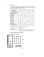
The inspection modes are assigned to the respective lamps as shown below.
Lamp
Type of inspection
Drum
Factory inspection mode
Alarm
Continuous grid pattern print mode
Ready
3 patterns print mode (grid
zip
black)
Data
NV-RAM value dump mode
Drum + Alarm
ROM code reprogramming mode (only
when the flash memory is fitted)
Alarm + Ready
RAM check
Ready + Data
4% density pattern print mode
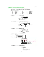
Details of the factory inspection mode are as follows.
This mode is used to check if the sensors in the printer are functioning correctly. In the
process of this inspection, the lamps and the switch on the control panel are also
checked. On entering this mode, the lamps show the status of the respective sensors as
follows.
Summary of Contents for HL-1070
Page 1: ...Download Free Service Manual and Resetter Printer at http printer1 blogspot com ...
Page 20: ...II 4 Fig 2 4 Download Free Service Manual and Resetter Printer at http printer1 blogspot com ...
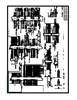
Page 96: ...CODE UK3958 000 B48K302 1CIR NAME A 3 Appendix 3 Main PCB Circuit Diagram 1 5 ...
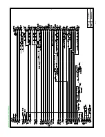
Page 97: ...CODE UK3958 000 B48K302 1CIR NAME A 4 Appendix 4 Main PCB Circuit Diagram 2 5 ...
Page 98: ...CODE UK3958 000 B48K302 1CIR NAME A 5 Appendix 5 Main PCB Circuit Diagram 3 5 ...
Page 99: ...CODE UK3958 000 B48K302 1CIR NAME A 6 Appendix 6 Main PCB Circuit Diagram 4 5 ...
Page 100: ...Appendix 7 Main PCB Circuit Diagram 5 5 CODE UK3958 000 B48K302 1CIR NAME A 7 ...
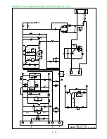
Page 101: ...Appendix 8 Driver PCB Circuit Diagram CODE UK3634000 B48K280CIR NAME A 8 ...
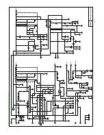
Page 106: ...Appendix 13 SR PCB Circuit Diagram CODE UK3653000 B48K284CIR NAME A 13 ...
Page 107: ...Apr 98 54U011BE0 PARTS REFERENCE LIST MODEL HL 1070 R LASER PRINTER ...
Page 241: ...APPENDIX A 11 HP LaserJet 6P EPSON FX 850 IBM Proprinter XL EPSON FX 850 PC 850 ...


