


iii
4. PACKING ........................................................................................................................ III-24
CHAPTER IV MAINTENANCE AND TROUBLESHOOTING........................... IV-1
1. INTRODUCTION...............................................................................................................IV-1
1.1 Initial Check .................................................................................................................................IV-1
1.2 Basic Procedure...........................................................................................................................IV-2
2. CONSUMABLE PARTS ....................................................................................................IV-2
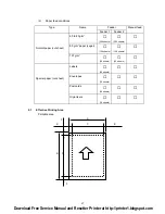
2.1 Drum Unit .....................................................................................................................................IV-2
2.2 Toner Cartridge............................................................................................................................IV-2
2.3 Periodical Replacement Parts......................................................................................................IV-3
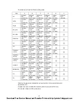
3. IMAGE DEFECTS .............................................................................................................IV-4
3.1 Image Defect Examples ...............................................................................................................IV-4
3.2 Troubleshooting Image Defects ...................................................................................................IV-5
3.3 Location of High-voltage Contacts and Grounding Contacts .....................................................IV-19
3.4 Location of Feed Roller Shaft and Grounding Contacts ............................................................IV-20
4. PAPER JAM ....................................................................................................................IV-21
5. TROUBLESHOOTING MALFUNCTIONS .......................................................................IV-22
6. INSPECTION MODE.......................................................................................................IV-27
6.1 Incorporated Inspection Modes..................................................................................................IV-27
6.2 Error Codes...............................................................................................................................IV-29
APPENDICES
1. Serial No. Descriptions ......................................................................................................A-1
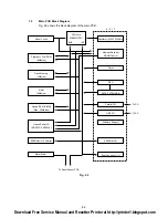
2. Connection Diagram ..........................................................................................................A-2
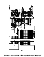
3. Main PCB Circuit Diagram, (1/5)........................................................................................A-3
4. Main PCB Circuit Diagram, (2/5)........................................................................................A-4
5. Main PCB Circuit Diagram, (3/5)........................................................................................A-5
6. Main PCB Circuit Diagram, (4/5)........................................................................................A-6
7. Main PCB Circuit Diagram, (5/5)........................................................................................A-7
8. Driver PCB Circuit Diagram ...............................................................................................A-8
9. Switch Panel/Solenoid, Bin/Relay PCB Circuit Diagram ....................................................A-9
10. Low-voltage Power Supply PCB Circuit Diagram (110 - 240V) ........................................A-10
11. Low-voltage Power Supply PCB Circuit Diagram (220 - 240V) ........................................A-11
12. High-voltage Power Supply PCB Circuit Diagram ............................................................A-12
13. SR PCB Circuit Diagram ..................................................................................................A-13
Download Free Service Manual and Resetter Printer at http://printer1.blogspot.com
Summary of Contents for HL-1070
Page 1: ...Download Free Service Manual and Resetter Printer at http printer1 blogspot com ...
Page 20: ...II 4 Fig 2 4 Download Free Service Manual and Resetter Printer at http printer1 blogspot com ...
Page 96: ...CODE UK3958 000 B48K302 1CIR NAME A 3 Appendix 3 Main PCB Circuit Diagram 1 5 ...
Page 97: ...CODE UK3958 000 B48K302 1CIR NAME A 4 Appendix 4 Main PCB Circuit Diagram 2 5 ...
Page 98: ...CODE UK3958 000 B48K302 1CIR NAME A 5 Appendix 5 Main PCB Circuit Diagram 3 5 ...
Page 99: ...CODE UK3958 000 B48K302 1CIR NAME A 6 Appendix 6 Main PCB Circuit Diagram 4 5 ...
Page 100: ...Appendix 7 Main PCB Circuit Diagram 5 5 CODE UK3958 000 B48K302 1CIR NAME A 7 ...
Page 101: ...Appendix 8 Driver PCB Circuit Diagram CODE UK3634000 B48K280CIR NAME A 8 ...
Page 106: ...Appendix 13 SR PCB Circuit Diagram CODE UK3653000 B48K284CIR NAME A 13 ...
Page 107: ...Apr 98 54U011BE0 PARTS REFERENCE LIST MODEL HL 1070 R LASER PRINTER ...
Page 241: ...APPENDIX A 11 HP LaserJet 6P EPSON FX 850 IBM Proprinter XL EPSON FX 850 PC 850 ...


