


CHAPTER 5 MAINTENANCE
5–9
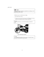
5. Install the toner cartridge into the new drum unit. For more
information, see
“REPLACING THE TONER CARTRIDGE”
in this
chapter.
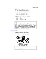
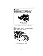
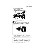
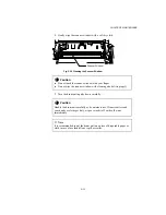
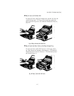
6. Install the new drum unit into the printer.
Fig. 5-15 Installing the Drum Unit
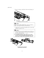
7. Close the top cover.
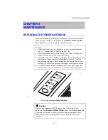
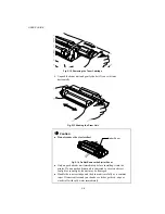
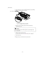
8. Turn on the power switch. The printer automatically ejects the starter
sheet. Ejecting this sheet resets the drum life alarm.
!
Caution
Do not open the top cover until the printer ejects the starter sheet
completely. It may cause the starter sheet to jam.
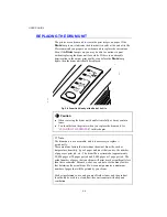
Fig. 5-16 Ejecting the Starter Sheet
Starter Sheet
Summary of Contents for HL-1070
Page 1: ...Download Free Service Manual and Resetter Printer at http printer1 blogspot com ...
Page 20: ...II 4 Fig 2 4 Download Free Service Manual and Resetter Printer at http printer1 blogspot com ...
Page 96: ...CODE UK3958 000 B48K302 1CIR NAME A 3 Appendix 3 Main PCB Circuit Diagram 1 5 ...
Page 97: ...CODE UK3958 000 B48K302 1CIR NAME A 4 Appendix 4 Main PCB Circuit Diagram 2 5 ...
Page 98: ...CODE UK3958 000 B48K302 1CIR NAME A 5 Appendix 5 Main PCB Circuit Diagram 3 5 ...
Page 99: ...CODE UK3958 000 B48K302 1CIR NAME A 6 Appendix 6 Main PCB Circuit Diagram 4 5 ...
Page 100: ...Appendix 7 Main PCB Circuit Diagram 5 5 CODE UK3958 000 B48K302 1CIR NAME A 7 ...
Page 101: ...Appendix 8 Driver PCB Circuit Diagram CODE UK3634000 B48K280CIR NAME A 8 ...
Page 106: ...Appendix 13 SR PCB Circuit Diagram CODE UK3653000 B48K284CIR NAME A 13 ...
Page 107: ...Apr 98 54U011BE0 PARTS REFERENCE LIST MODEL HL 1070 R LASER PRINTER ...
Page 241: ...APPENDIX A 11 HP LaserJet 6P EPSON FX 850 IBM Proprinter XL EPSON FX 850 PC 850 ...


