


II-1
CHAPTER II THEORY OF OPERATION
1. ELECTRONICS
1.1
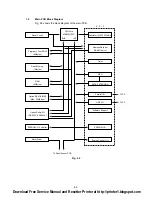
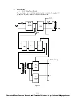
General Block Diagram
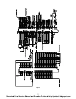
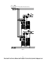
Fig. 2.1 shows a general block diagram of the HL-1070 printer.
Optional RAM(SIMM)
(Max. 32Mbytes)
Optional I/F Board
( RS-232C)
Expansion Memory I/O
Expansion I/O
Parallel
Video Control Block
Interface Block
Engine Control Block
Operation Block
(Operation Panel)
Control System
Low-voltage Power
Supply Block
High-voltage Power
Supply Block
Laser Scanner Unit
Drive Block
(Stepping Motor)
Drum Unit
Transfer Block
Developing
Block
Drum
Charging
Block
Cleaner
Block
External Device
External Device
Paper Tray Unit
Paper Feeder
Manual Feed
Fixing Unit
Paper Eject Block
Paper Feed System
Image Generation System
Toner Cartridge
Erase Lamp
External Device
USB
Fig. 2.1
Download Free Service Manual and Resetter Printer at http://printer1.blogspot.com
Summary of Contents for HL-1070
Page 1: ...Download Free Service Manual and Resetter Printer at http printer1 blogspot com ...
Page 20: ...II 4 Fig 2 4 Download Free Service Manual and Resetter Printer at http printer1 blogspot com ...
Page 96: ...CODE UK3958 000 B48K302 1CIR NAME A 3 Appendix 3 Main PCB Circuit Diagram 1 5 ...
Page 97: ...CODE UK3958 000 B48K302 1CIR NAME A 4 Appendix 4 Main PCB Circuit Diagram 2 5 ...
Page 98: ...CODE UK3958 000 B48K302 1CIR NAME A 5 Appendix 5 Main PCB Circuit Diagram 3 5 ...
Page 99: ...CODE UK3958 000 B48K302 1CIR NAME A 6 Appendix 6 Main PCB Circuit Diagram 4 5 ...
Page 100: ...Appendix 7 Main PCB Circuit Diagram 5 5 CODE UK3958 000 B48K302 1CIR NAME A 7 ...
Page 101: ...Appendix 8 Driver PCB Circuit Diagram CODE UK3634000 B48K280CIR NAME A 8 ...
Page 106: ...Appendix 13 SR PCB Circuit Diagram CODE UK3653000 B48K284CIR NAME A 13 ...
Page 107: ...Apr 98 54U011BE0 PARTS REFERENCE LIST MODEL HL 1070 R LASER PRINTER ...
Page 241: ...APPENDIX A 11 HP LaserJet 6P EPSON FX 850 IBM Proprinter XL EPSON FX 850 PC 850 ...


