2-12
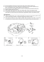
25. Pass the cassette lever spring over the lever shaft, and then attach it with the retaining ring.
26. Pass the cassette lever over the lever shaft, hook the cassette lever spring onto the cassette lever (as
shown in the illustration below), and then attach it with the retaining ring.
27. Secure the washer and the cassette release lever assy to the driving lever assy with the retaining ring.
28. Install the cassette release lever spring.
29. Fit the cassette button spring into the notch in the cassette button. (Refer to the illustration below).
30. Turn the wheel of the shutter to move the driving lever assy and cassette release lever assy to their lowest
points. Attach the cassette button (with cassette button spring attached). (Refer to the illustration below.)
Assembly Points
28. When the cassette release lever is lowered and released, it should return to its previous position under
the force of the spring. At that time, check that the thread cutter operates smoothly.
30. Check that the cassette lever assy operates smoothly when the wheel of the shutter is turned and
the cassette button is pressed when the driving lever assy and cassette release lever assy are raised.
Summary of Contents for E-100
Page 1: ... 3 2002 ...
Page 4: ...1 1 1 TECHNICAL DIAGRAMS ...
Page 6: ...1 3 4 CONTROL SYSTEM BLOCK DIAGRAM ...
Page 23: ...2 15 3 LEAD WIRE ARRNGEMENT For details refer to the instructions of wiring ...
Page 31: ...3 3 Main PC board ASSY REG board ASSY Sensor board ASSY ...
Page 32: ...4 0 IV 1 PARTS CATALOGUE 4 1 2 OTHER PARTS 4 3 ...
Page 34: ...4 2 ...
Page 36: ...4 4 ...
Page 37: ...E 100 E 100P E 100M XXXXXXX ...


