


2-4
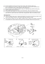
15. Remove the three E2 retaining rings and the E3 retaining ring, and then remove the thread cutter lever assy,
and the two thread cutter links.
16. Remove the E3 retaining ring.
17. Remove the screw, and then remove the thread cutter assy.
18. Remove the screw, and then remove the thread cutter switch assy.
19. Remove the three screws from the bottom of the under cover assy, and then remove the under cover assy.
Disassembly Points
16. Since the E3 retaining ring is only used to position the thread cutter lever assy, not removing
the retaining ring does not prevent other parts from being removed.
Summary of Contents for E-100
Page 1: ... 3 2002 ...
Page 4: ...1 1 1 TECHNICAL DIAGRAMS ...
Page 6: ...1 3 4 CONTROL SYSTEM BLOCK DIAGRAM ...
Page 23: ...2 15 3 LEAD WIRE ARRNGEMENT For details refer to the instructions of wiring ...
Page 31: ...3 3 Main PC board ASSY REG board ASSY Sensor board ASSY ...
Page 32: ...4 0 IV 1 PARTS CATALOGUE 4 1 2 OTHER PARTS 4 3 ...
Page 34: ...4 2 ...
Page 36: ...4 4 ...
Page 37: ...E 100 E 100P E 100M XXXXXXX ...