


2-14
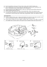
35. Insert the 6 connectors into the upper cover assy.
36. Secure the upper cover assy to the under cover assy with the three screws. Refer to the bottom-view
diagram below. (LEAD WIRE ARRANGEMENT (page 2-15); For details, refer to the instructions of wiring.)
Note
36. Do not insert a screw into the notch for the needle plate.
Summary of Contents for E-100
Page 1: ... 3 2002 ...
Page 4: ...1 1 1 TECHNICAL DIAGRAMS ...
Page 6: ...1 3 4 CONTROL SYSTEM BLOCK DIAGRAM ...
Page 23: ...2 15 3 LEAD WIRE ARRNGEMENT For details refer to the instructions of wiring ...
Page 31: ...3 3 Main PC board ASSY REG board ASSY Sensor board ASSY ...
Page 32: ...4 0 IV 1 PARTS CATALOGUE 4 1 2 OTHER PARTS 4 3 ...
Page 34: ...4 2 ...
Page 36: ...4 4 ...
Page 37: ...E 100 E 100P E 100M XXXXXXX ...