2-10
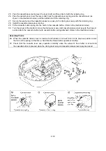
10. Secure the Y pulse motor assy with the two screws.
11. Secure the idle gear with the retaining ring.
12. Secure the main motor assy with the two screws. (Position the main motor assy so that the red lead wire is
almost at the top.)
13. Secure the lead wires for the main motor assy and the Y pulse motor assy with the band. (LEAD WIRE
ARRANGEMENT (page 2-15); For details, refer to the instructions of wiring.)
14. Pass the Y guide shaft through the hole in the Y carriage, and then secure the guide shaft with the two
retaining rings.
15. Secure the shutter to the driving cam shaft assy with the retaining ring, and then secure the driving cam
shaft assy to the base plate assy with the retaining ring.
16. Secure the driving lever assy, the two collars, and the polyester slider to the base plate assy with the two
retaining rings. (The driving lever assy should be moved carefully.)
17. Insert the pin into the driving cam shaft.
18. Secure the driving cam to the driving cam shaft with the retaining ring.
Assembly Points
11. If the driving cam that is installed next does not fit because of the position of the retaining ring, move the
opening of the retaining ring toward the driving cam.
12. Using the screws, move the position of the main motor assy to adjust the backlash between the motor
gear and the idle gear. (backlash of 0.1 to 0.2 mm)
18. When installing the driving cam, position the shutter at the right, and then align the
φ
2 projection on the
driving cam at the top as shown in the illustration.
Summary of Contents for E-100
Page 1: ... 3 2002 ...
Page 4: ...1 1 1 TECHNICAL DIAGRAMS ...
Page 6: ...1 3 4 CONTROL SYSTEM BLOCK DIAGRAM ...
Page 23: ...2 15 3 LEAD WIRE ARRNGEMENT For details refer to the instructions of wiring ...
Page 31: ...3 3 Main PC board ASSY REG board ASSY Sensor board ASSY ...
Page 32: ...4 0 IV 1 PARTS CATALOGUE 4 1 2 OTHER PARTS 4 3 ...
Page 34: ...4 2 ...
Page 36: ...4 4 ...
Page 37: ...E 100 E 100P E 100M XXXXXXX ...


