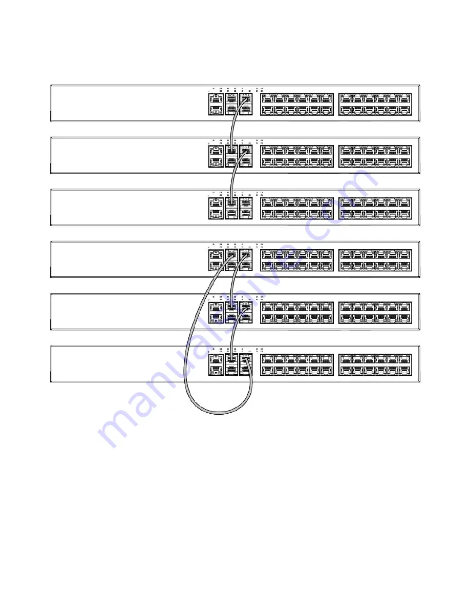
FIGURE 27
Linear and ring stacking topologies using one port per trunk
Connecting devices in a traditional stack
Brocade ICX 6430 and ICX 6450 Stackable Switches Hardware Installation Guide
Part Number: 53-1003617-03
37
Page 1: ...HARDWARE INSTALLATION GUIDE Brocade ICX 6430 and ICX 6450 Stackable Switches Hardware Installation Guide Part Number 53 1003617 03 Publication Date 15 June 2017...
Page 2: ...atures that may not be currently available Contact a Brocade sales office for information on feature and product availability Export of technical data contained in this document may require an export...
Page 3: ...Specifying a port address 18 Port system and power status LEDs 19 Power supplies 22 Power supply usage 23 ICX 6430 and ICX 6450 Installation 25 Items included with the ICX 6430 and ICX 6450 devices 25...
Page 4: ...ions 54 Lifting precautions 54 Power precautions 54 Preparing the installation site 55 Rack mount installation considerations 55 Installing the device 55 Desktop installation 56 Mounting an external p...
Page 5: ...ling a new copper or fiber optic transceiver 87 Cabling a fiber optic transceiver 88 Cleaning the fiber optic connectors 89 Brocade ICX 6430 and ICX 6450 Stackable Switches Technical Specifications 91...
Page 6: ...ublic of Korea 101 VCCI statement 101 Cautions and Danger Notices 103 Cautions 103 General cautions 103 Electrical cautions 104 Danger Notices 105 General dangers 106 Electrical dangers 106 Dangers re...
Page 7: ...vice might reboot CAUTION A Caution statement alerts you to situations that can be potentially hazardous to you or cause damage to hardware firmware software or data DANGER A Danger statement indicate...
Page 8: ...rocade website to locate related documentation for your product and additional Brocade resources White papers data sheets and the most recent versions of Brocade software and hardware manuals are avai...
Page 9: ...Continental US 1 800 752 8061 Europe Middle East Africa and Asia Pacific 800 AT FIBREE 800 28 34 27 33 Toll free numbers are available in many countries For areas unable to access a toll free number 1...
Page 10: ...Brocade ICX 6430 and ICX 6450 Stackable Switches Hardware Installation Guide 10 Part Number 53 1003617 03...
Page 11: ...re are no enhancements in this edition Supported Software For information about the features supported on a hardware platform refer to the appropriate Features and Standards Support Matrix document Br...
Page 12: ...Brocade ICX 6430 and ICX 6450 Stackable Switches Hardware Installation Guide 12 Part Number 53 1003617 03...
Page 13: ...wing models ICX 6430 24 24 10 100 1000 Mbps copper ports and 4 1 Gbps SFP fiber uplink and stacking ports ICX 6430 24P 24 10 100 1000 Mbps PoE copper ports and 4 1 Gbps SFP fiber uplink and stacking p...
Page 14: ...ts and 4 ports with 1 or 10 Gbps SFP fiber uplink and stacking ports ICX 6450 48 48 10 100 1000 Mbps copper ports and 4 ports with 1 or 10 Gbps SFP fiber uplink and stacking ports ICX 6450 48P 48 10 1...
Page 15: ...nt interfaces and a system reset button on the front panel Console management interface RJ 45 serial port Out of band management interface RJ 45 port Reset button These RJ 45 management ports are loca...
Page 16: ...ort 4 Slot 1 10 100 1000 Mbps ports Console management interface The console management interface is an RJ 45 serial port that allows you to configure and manage the device using a third party termina...
Page 17: ...s 1 24 SFP and SFP ports 1 4 ICX 6450 24P 10 100 1000 Mbps ports 1 24 SFP and SFP ports 1 4 ICX 6450 48 10 100 1000 Mbps ports 1 48 SFP and SFP ports 1 4 ICX 6450 48P 10 100 1000 Mbps ports 1 48 SFP a...
Page 18: ...ng port or a management port Specifying a data port The port address format is stack unit slot port where stack unit Specifies the stack unit ID For the ICX 6430 the range is from 1 through 4 For the...
Page 19: ...and receiving user packets Off A link is not established with a remote port PoE PoE 1 24 48 On Green The port is providing PoE or PoE power to a connected device Off The port is not providing PoE or P...
Page 20: ...S1 and EPS2 power supplies are operating normally Yellow EPS1 and EPS2 power supply fault Off EPS1 and EPS2 off or not present PWR Power Green Power supply is operating normally Yellow Power supply fa...
Page 21: ...status LEDs on the 24 port models and 48 port models FIGURE 18 Power status LED on the ICX 6430 24 model 1 Power status LEDs Power status LED on the ICX 6430 48 and ICX 6430 48P models NOTE The locat...
Page 22: ...on the rear panel of the device for the AC power cord The connector labeled EPS is for the optional external power supply cord that can provide power to the device in the event the internal power sup...
Page 23: ...ystem power portion of the EPS can be used for internal system power redundancy TABLE 6 AC power supply and PoE and PoE usage Model Maximum power draw from AC line input Watts Number of PoE ports supp...
Page 24: ...Brocade ICX 6430 and ICX 6450 Stackable Switches Hardware Installation Guide 24 Part Number 53 1003617 03...
Page 25: ...430 or ICX 6450 device Rack mounting kit containing two L shaped mounting brackets and six sink head screws Wall mounting kit containing two wall mount screws and two plastic anchors for ICX 6430 24 I...
Page 26: ...power source that adheres to the regulatory requirements outlined in this manual Powering on the system on page 48 Installation precautions Follow all precautions when installing a device General prec...
Page 27: ...lled at the site For information about supported SFP and SFP transceivers and cable lengths and types refer to the product data sheet Installation location Devices can be mounted in a standard 19 inch...
Page 28: ...n page 91 Mechanical loading Do not place any equipment on top of a rack mounted unit Circuit overloading Be sure that the supply circuit to the rack assembly is not overloaded Grounding Rack mounted...
Page 29: ...ultiple devices place each device squarely on top of the one below Rack mount installation The devices use stationary mounting when mounted in a rack DANGER Make sure the rack housing the device is ad...
Page 30: ...for ICX 6430 and ICX 6450 devices 3 Remove the two post rack kit from the shipping carton The kit contains four rack mounting screws and four cage nuts 4 Insert the cage nuts in the two post rack whe...
Page 31: ...installed on four post racks FIGURE 23 Installing the device in a two post rack 1 Rack mounting screws 2 Cage nuts 6 If installing a single device only proceed to Powering on the system on page 48 If...
Page 32: ...vices Brocade recommends that you wall mount the device with the port side down NOTE The ICX 6430 48 ICX 6430 48P ICX 6450 48 and ICX 6450 48P devices cannot be wall mounted Complete the following ste...
Page 33: ...IGURE 24 Attaching the wall mount brackets for ICX 6430 24 devices 3 Drill two holes on the wall where you want to mount the device 4 Hammer two wall mount anchors into the holes on the wall Installin...
Page 34: ...aditional stacks A stack is a group of devices Brocade stackable units and their connected stacking links that are connected so that the stack is managed as a single entity A traditional stack contain...
Page 35: ...not configured for trunking On the ICX 6450 ports 1 and 3 are 10 Gbps ports Without a license at bootup ICX 6450 ports 2 and 4 come up in 10 Gbps port speed in an error disabled state To enable ports...
Page 36: ...n can use one port or two ports per trunk For example in a four unit stack using a linear topology unit 1 connects to unit 2 unit 2 to unit 3 and unit 3 to unit 4 In ring stack topology there is an ex...
Page 37: ...Linear and ring stacking topologies using one port per trunk Connecting devices in a traditional stack Brocade ICX 6430 and ICX 6450 Stackable Switches Hardware Installation Guide Part Number 53 1003...
Page 38: ...g both ports in each trunk FIGURE 29 Ring stacking topology using both ports in each trunk Connecting devices in a traditional stack Brocade ICX 6430 and ICX 6450 Stackable Switches Hardware Installat...
Page 39: ...10 to ICX 6450 ICX 6450 SFP Front 2 1 4 10 Gbps Peripheral to backbone ICX 6450 to ICX 6610 Peripheral to peripheral ICX 6450 to ICX 6450 ICX 6610 stacking ports and trunks This section discusses the...
Page 40: ...t 1 to Port 6 Port 1 to Port 7 Port 2 to Port 2 Port 2 to Port 1 If you connect both ports in a trunk both ports must connect to both ports of one trunk on another device NOTE If you use the Secure Se...
Page 41: ...IGURE 31 SFP ports on the front panel of the 24 port model of an ICX 6610 device 1 Slot 3 10 Gbps SFP ports 1 8 2 Slot 1 10 100 1000 Mbps ports FIGURE 32 SFP ports on the front panel of the 48 port mo...
Page 42: ...port speed you must purchase the ICX6450 2X10G LIC POD license For more information about enabling ports 2 and 4 to 10 Gbps port speed refer to the FastIron Ethernet Switch Administration Guide Trunki...
Page 43: ...stack ICX 6450 devices are peripheral units There can be one to six ICX 6450 devices in a mixed stack Peripheral devices can form one or more substacks A substack is a topology that is formed by ICX...
Page 44: ...evice and the first ICX 6610 device is connected to the last ICX 6450 device There is one substack that contains three peripheral devices FIGURE 34 Topology 1 single ring Topology 2 Dual ring In the f...
Page 45: ...450 peripheral devices in two substacks Each substack contains three peripheral devices One substack is connected to one ICX 6610 device to form a linear topology The other substack is connected to ea...
Page 46: ...ntains all six peripheral devices Topology 4 shows that you can have a mixed stack with only one ICX 6610 device although this configuration does not provide high availability or resiliency for the st...
Page 47: ...6610 devices in a mixed stack backbone using both ports ports 1 and 2 in trunk 0 of each ICX 6610 device Ports 1 and 2 in the top device connect to ports 1 and 2 in the bottom device respectively FIG...
Page 48: ...stance stacking use fiber optic cables to connect the devices in a stack Contact your Brocade representative for information about supported fiber optic cables and distances Powering on the system Aft...
Page 49: ...zed by the device The 54 V PoE power source is not used by the device NOTE The internal power supply of the ICX 6430 or ICX 6450 device is not a field replaceable unit FRU The devices must be shut dow...
Page 50: ...line cord draws power from power outlet DC line cord provides power to the attached device Thermal overload protection prevents the ICX 6400 EPS1500 from overheating if a thermal overload occurs Over...
Page 51: ...rear panel 1 Fans 2 External power sockets 1 3 3 AC power socket LEDs The following figure shows the location of the LEDs on the ICX 6400 EPS1500 ICX 6400 EPS1500 external power supply Brocade ICX 64...
Page 52: ...V and 54 V of power Red The port is not delivering power to the device Power failure at 12 V and 54 V of power EPS 3 Green The power supply is operating normally The port is providing power to the co...
Page 53: ...manage the system using the CLI through Telnet or Brocade Network Advisor Summary of installation tasks Follow the steps in the following table to install your device Details for each of these steps a...
Page 54: ...er DANGER Mount the devices you install in a rack as low as possible Place the heaviest device at the bottom and progressively place lighter devices above Power precautions CAUTION Use a separate bran...
Page 55: ...om power lines fluorescent lighting fixtures and other sources of electrical interference such as radios and transmitters Provide a separate grounded power outlet that provides 100 to 240 VAC 50 60 Hz...
Page 56: ...on all sides for proper airflow Mounting an external power supply in a rack DANGER Make sure the rack housing the device is adequately secured to prevent it from becoming unstable or falling over Com...
Page 57: ...y using six sink head screws FIGURE 44 Attaching the mounting brackets for the ICX 6400 EPS1500 3 Mount the external power supply in a rack using four rack mounting screws Installing the device Brocad...
Page 58: ...for the EPS cord is used to hold the EPS cord securely in place when connecting to multiple devices This is an optional installation that will help to prevent the EPS cord from accidentally unplugging...
Page 59: ...nd faceplate 1 Using a Phillips screwdriver remove the two screws on the EPS faceplate of the external power receptacle as illustrated in the figure below Installing the device Brocade ICX 6430 and IC...
Page 60: ...as illustrated in the figure below FIGURE 47 Assembling the cable tie and wire saddle 1 Cable tie 2 Wire saddle Installing the device Brocade ICX 6430 and ICX 6450 Stackable Switches Hardware Install...
Page 61: ...ure below FIGURE 48 Complete assembly of cable tie and wire saddle 1 Wire saddle 4 Open the wire saddle hook and plug the EPS cord into the external power receptacle Installing the device Brocade ICX...
Page 62: ...end of the AC cord to the AC receptacle on the device and the other end to a grounded power outlet 2 Connect one end of an EPS cord to the external power receptacle on the device and the other end to...
Page 63: ...cord to the AC receptacle on the external power supply and the other end to a grounded power outlet Installing the device Brocade ICX 6430 and ICX 6450 Stackable Switches Hardware Installation Guide P...
Page 64: ...PS Input port on the ICX 6430 or ICX 6450 device 4 AC power supply for ICX 6400 EPS1500 2 ICX 6430 and ICX 6450 devices 5 ICX 6400 EPS1500 3 AC power supplies for ICX 6430 or ICX 6450 devices 6 Output...
Page 65: ...lugging it into a power source and verifying that it passes the self test 1 Connect the power cord supplied with the device to the power connector on the power supply on the rear of the device 2 Inser...
Page 66: ...Brocade ICX 6430 and ICX 6450 Stackable Switches Hardware Installation Guide 66 Part Number 53 1003617 03...
Page 67: ...Before attaching equipment to the device you must configure an interface IP address to the subnet on which the device will be located Initial IP address configuration is performed using the CLI with...
Page 68: ...not see the prompt make sure the cable is securely connected to your PC and to the Brocade system Check the settings in your terminal emulation program In addition to the previously configured sessio...
Page 69: ...the CLI by entering the following command device configure terminal 3 Enter the following command to set the Super User password device config enable super user password joe NOTE You must set the Supe...
Page 70: ...nt mask bits By default the CLI displays network masks in classical IP address format for example 255 255 255 0 You can change the display to the prefix format Refer to the FastIron Ethernet Switch Ad...
Page 71: ...command at the CLI Privileged EXEC level prompt and then press Enter This command erases the factory test configuration if still present device erase startup config CAUTION Use the erase startup conf...
Page 72: ...ss to a loopback interface Loopback interfaces are always up regardless of the states of physical interfaces They can add stability to the network because they are not subject to route flap problems t...
Page 73: ...of untagged ports to the VLAN The router interface command creates virtual interface 1 as the routing interface for the VLAN The last two commands change to the interface configuration level for the...
Page 74: ...rossover cable NOTE The 802 3ab standard automatic MDI or MDIX detection calls for automatic negotiation of the connection between two 1000Base T ports In this case a straight through cable may work j...
Page 75: ...t For more information about this feature and how to configure it refer to the Brocade FastIron Security Configuration Guide Connecting a network device to a fiber port For direct attachment from the...
Page 76: ...Gbps optical transceivers are not supported on ICX 6430 devices You can configure your device to monitor optical transceivers in the system either globally or by specified port When this feature is e...
Page 77: ...that the connection to the other network device has been properly made Also make certain that the other network device is powered on and operating correctly Verify that the port has not been disabled...
Page 78: ...ther network device is powered on and operating correctly Verify that the transmit port on the device is connected to the receive port on the other network device and that the receive port on the devi...
Page 79: ...other network device has been properly made Also make certain that the other network device is powered on and operating correctly Verify that the transmit port on the device is connected to the receiv...
Page 80: ...cade device can reach another device enter a command similar to the following at any level of the CLI on the device device traceroute 10 33 4 7 Syntax traceroute host ip addr maxttl value minttl value...
Page 81: ...the shutdown level and the device will shut down in five minutes The system restarts five minutes after the device reaches the temperature shutdown level TABLE 15 Temperature thresholds Model Warning...
Page 82: ...te LEARNING FwdDlyExpiry 0d00h00m26s I STP VLAN 1 Port 1 2 3 STP State FORWARDING FwdDlyExpiry 0d00h00m26s I STP VLAN 1 Port 1 1 1 STP State FORWARDING FwdDlyExpiry 0d00h00m24s I STP VLAN 1 Port 1 2 3...
Page 83: ...log message is displayed when the temperature reaches the warning level Temperature is over warning level on stack unit 1 Temperature shutdown levels When the temperature crosses the critical shutdown...
Page 84: ...s For example to remove entries for the MAC address 00 00 00 in all VLANs enter the following command at the Privileged EXEC level of the CLI Brocade clear mac address 00 00 00 Syntax clear mac addres...
Page 85: ...ICX 6430 or ICX 6450 device is powered on and running Removing a copper or fiber optic module You can remove a copper or fiber SFP transceiver from a slot while the ICX 6430 or ICX 6450 device is pow...
Page 86: ...latch 1 Bail latch NOTE The bail latch may be attached to either the top or the bottom of the SFP transceiver 4 Grasp the bail latch and pull the copper or fiber optic module out of the port FIGURE 54...
Page 87: ...Gbps port speed The workaround is to disable the port and then re enable the port through the CLI or unplug and plug in the cable DANGER For safety reasons the ESD wrist strap should contain a series...
Page 88: ...ore cabling a fiber optic transceiver Brocade strongly recommends cleaning the cable connectors and the port connectors 2 Gently insert the cable connector a tab on each connector should face upward i...
Page 89: ...and reconnect them Dust can accumulate in the connectors and cause problems such as reducing the optic launch power To clean the fiber cable connectors Brocade recommends using a fiber optic reel typ...
Page 90: ...Brocade ICX 6430 and ICX 6450 Stackable Switches Hardware Installation Guide 90 Part Number 53 1003617 03...
Page 91: ...g Side to back airflow or free air circulation fanless ICX 6430 24 System architecture ICX 6430 4 stackable ICX 6450 8 stackable Ethernet System component Description Ethernet ports 24 and 48 port 10...
Page 92: ...3 cm 17 4 inches 37 cm 14 6 inches 5 kg 11 lb 6 kg 13 lb ICX 6430 24P 4 3 cm 1 7 inches 44 3 cm 17 4 inches 24 cm 9 4 inches 4 6 kg 10 lb 5 5 kg 11 6 lb ICX 6430 48P 4 3 cm 1 7 inches 44 3 cm 17 4 in...
Page 93: ...tput power rating DC Input voltage Input line frequency Maximum input current Input line protection Maximum inrush current ICX 6430 24 36 Watts 100 240 VAC 50 60 Hz 0 9 A Line fused 250 A maximum at 2...
Page 94: ...38 BTU hr 2 5 A N A 1 ICX 6450 48 2 A 68 88 W 235 03 BTU hr 0 833 A N A 1 ICX 6450 48P 10 A 958 02 W 3268 9 BTU hr 4 167 A N A 1 Data port specifications Ethernet Model Port type Number of ports Descr...
Page 95: ...ble to 10 GbE and 2 1 GbE 10 GbE SFP uplink stacking ports ICX 6450 48P PoE ports with internal and external power supplies 48 48 port 1 GbE switch PoE 2 1 GbE SFP upgradable to 10 GbE and 2 1 GbE 10...
Page 96: ...e in electrical and electronic equipment EU RoHS 2012 19 EU Waste electrical and electronic equipment EU WEEE 94 62 EC packaging and packaging waste EU 2006 66 EC batteries and accumulators and waste...
Page 97: ...t all the other components are functioning properly Power and cooling problems If the power indicator does not turn on when the power cord is plugged in you may have a problem with the power outlet po...
Page 98: ...Brocade ICX 6430 and ICX 6450 Stackable Switches Hardware Installation Guide 98 Part Number 53 1003617 03...
Page 99: ...hat this system conforms to the provisions of the following European Council directives laws and standards Electromagnetic Compatibility EMC Directive 2004 108 EEC Low Voltage Directive LVD 2006 95 EC...
Page 100: ...an Interference Causing Equipment Regulations ICES 003 Class A Cet appareil num rique de la classe A est conforme la norme NMB 003 du Canada China CC statement Canadian requirements Brocade ICX 6430 a...
Page 101: ...user will be required to correct the interference at the user s own expense Germany Machine noise information regulation 3 GPSGV the highest sound pressure level value is 70 0 dB A in accordance with...
Page 102: ...Brocade ICX 6430 and ICX 6450 Stackable Switches Hardware Installation Guide 102 Part Number 53 1003617 03...
Page 103: ...104 F installiert werden MISE EN GARDE N installez pas le dispositif dans un environnement o la temp rature d exploitation ambiante risque de d passer 40 C 104 F PRECAUCI N No instale el instrumento...
Page 104: ...to save the running configuration to the startup config file VORSICHT Verwenden Sie den Befehl Erase startup config L schen Startup Konfig nur f r neue Systeme Wenn Sie diesen Befehl in ein bereits ko...
Page 105: ...Compare esta suma con el l mite nominal para el circuito Las capacidades nominales de corriente m ximas est n generalmente impresas en los instrumentos cerca de los conectores de corriente de entrada...
Page 106: ...quires a different power cord than the one supplied with the device make sure you use a power cord displaying the mark of the safety agency that defines the regulations for power cords in your country...
Page 107: ...ne Weise gesichert ist so dass das Gestell oder der Schrank nicht wackeln oder umfallen kann DANGER V rifiez que le b ti abritant le dispositif est bien fix afin qu il ne devienne pas instable ou qu i...
Page 108: ...PELIGRO Todas las interfaces de fibra ptica utilizan l ser de clase 1 Danger Notices Brocade ICX 6430 and ICX 6450 Stackable Switches Hardware Installation Guide 108 Part Number 53 1003617 03...