background image

                                                                                                                                                                                          55

3

3

SECTION 3 - UNIT DISASSEMBLY

Remove Access Door

1. Insert key into lock of access door handle and turn 

key one quarter-turn clockwise (Figure 1).

Figure 1

 2. Grasp door handle and turn one quarter-turn 

counterclockwise to open. Remove key.

 3. Open door enough to clear its jambs and lift the door 

from its hinges.

Remove Power and Fuel Source

1. Turn OFF the unit and remove the 15 Amp fuse.

 2. Turn OFF and disconnect UTILITY power from 

generator.

 3. Turn OFF and disconnect the fuel supply. Plug both 

openings to prevent contamination from entering the 
fuel inlet or the fuel line.

Remove Roof

Remove the four screws and lift off (

A

, Figure 2).

Figure 2

Remove Battery

1. Disconnect the negative (

-

) battery cable.

 2. Disconnect the positive (

+

) battery cable.

 3. Remove the battery and set aside.

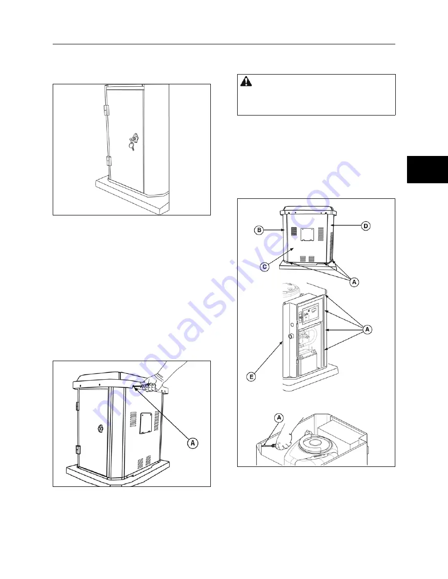
Remove Side Panels

1. Remove screws (

A

, Figure 3), attaching control side 

panel (

B

), access door (

C

), and exhaust panel (

D

). 

One panel (

E

) will not be removed.

Figure 3

 2. Tilt panels out (away) from unit while pulling panels 

up and out of base.

WARNING 

Battery posts, terminals, and related 

accessories contain lead and lead compounds, chemicals 
known to the State of California to cause cancer and 
reproductive harm. Wash hands after handling.

Not 

for  

Reproduction

Summary of Contents for 040298

Page 1: ...Home Generator System Manual 278994GS Rev BRIGGS STRATTON SERVICE TROUBLESHOOTING MANUAL HOME GENERATOR SYSTEM 7kW N o t f o r R e p r o d u c t i o n...

Page 2: ...ernative methods or procedures may pose risk to personal safety and the safety and or reliability of the engine and are not endorsed or recommended by Briggs Stratton All information illustrations and...

Page 3: ...1 2 3 4 SECTION 1 Safety Maintenance and Adjustments SECTION 2 Troubleshooting SECTION 3 Unit Disassembly SECTION 4 Generator Specifications N o t f o r R e p r o d u c t i o n...

Page 4: ...THISPROPER SERVICE AND REPAIR IS IMPORTANT TO THE SAFE ECONOMICAL AND RELIABLE MODELS COVERED IN THIS MANUAL 040298 040298A 040301 040315 040320 N o t f o r R e p r o d u c t i o n...

Page 5: ...a hazard symbol may be used to represent the type of hazard DANGER indicates a hazard which if not avoided will result in death or serious injury WARNING indicates a hazard which if not avoided could...

Page 6: ...from utility power can result in death or injury to electric utility workers due to back feed of electrical energy When using generator for backup power notify utility DO NOT touch bare wires or bare...

Page 7: ...llow equipment to cool before touching DO NOT install the generator closer than 5 feet 1 5m from any combustibles or structures with combustible walls having a fire rating of less than 1 hour Keep at...

Page 8: ...for water drainage Install the unit in a location where sump pump discharge rain gutter down spouts roof run off landscape irrigation or water sprinklers will not flood the unit or spray the enclosure...

Page 9: ...y Generator C Engine Exhaust D Combustible Material or Structure with a Fire Resistance Rating of less than 1 hour E Any structure or material DO NOT connect A and or D to E Lifting the Generator The...

Page 10: ...access openings and a removable roof Figure 1 Roof A Access Door B Side Panel C Access Panel D Access Cover for Oil Drain and Oil Filter E Each generator is supplied with a set of identical keys These...

Page 11: ...sh panel until flush with sides 3 Replace panel screw s 4 Replace roof and screws To open access door 1 Insert key into lock of access door handle and turn key one quarter turn clockwise Figure 5 Figu...

Page 12: ...y type UL approved filter element and foam pre clean er to protect engine by filtering dust and debris out of intake air F Engine Label Identifies engine model type and code numbers G Oil Fill Cap Dip...

Page 13: ...ility power is restored AUTO lets the engine stabilize internal temperatures shuts off the generator and waits for the next utility power outage OFF position turns off running generator prevents unit...

Page 14: ...ith the generator The remote LED will turn on and off in a series of blinks if certain faults are detected in the generator D 12 Volt DC 5 Amp Output Auxiliary power supply Use 12VDC and GND to connec...

Page 15: ...cuum Tester Natural gas fuel supply pressure at the generator fuel inlet port should be between 5 to 7 inches of water column in W C at full load with all gas appliances turned on and operating LP gas...

Page 16: ...11 Reinstall brass cover E 12 Using Insertion Tool 19570 remove existing jet from lower carburetor inlet H 13 Install new jet using Insertion Tool 19570 14 Replace 3 4 brass cap F 15 Reinstall enclosu...

Page 17: ...t breaker that sends utility power to the automatic transfer switch NOTICE When utility voltage is lost and the sensor has timed out the engine will crank and start Let the system go through its entir...

Page 18: ...or Maintenance Before performing any generator maintenance always perform the following steps 1 Set generator s circuit breaker to its OFF position 2 Set control panel system switch to OFF 3 Remove 15...

Page 19: ...gs into the cylinder heads Torque to 180 lb in 20 Nm Oil Service Checking the Oil Level Check the engine oil level as follows 1 Remove the roof to the unit to access the oil fill and dipstick location...

Page 20: ...e the foam pre cleaner from filter cartridge and wash in soapy water Rinse thoroughly and allow to air dry 4 Remove the foam filter and clean 5 Reinstall foam filter and clean air filter cartridge Mak...

Page 21: ...the gas at the installation site may be different from the fuel used at the factory Minimum generator frequency is 57 Hz at full load Maximum generator frequency is 62 0 62 5 Hz at no load To adjust...

Page 22: ...frequency should be above 57 0 Hz 3240 RPM 11 If frequency is below 57 0 Hz 3240 RPM use the Tang Bender or needle nose pliers to bend spring anchor tang until frequency is above 57 0 Hz 3240 RPM 12...

Page 23: ...19 1 1 N o t f o r R e p r o d u c t i o n...

Page 24: ...20 1 1 N o t f o r R e p r o d u c t i o n...

Page 25: ...ne Cool Down Timer Fault Code FC Detection with Automatic Shutdown Fault Indication Display LED Hour Meter Power During Control Panel Fault Conditions When the Home Generator System experiences a faul...

Page 26: ...240 VAC from UTILITY power The 10 pin connector C is used for optional generator features In addition the control panel also has connections for E1 and E2 D which sense 240VAC from the generator and...

Page 27: ...d 44 to the circuit breaker Any electrical load connected to generator will complete the circuit 120VAC and frequency signals are delivered from the stator winding via wires 11A and 22A to the voltage...

Page 28: ...hour meter and shows the total elapsed running time of the generator Following is a list of possible fault codes FC_1 Low Battery Voltage FC_2 Low Oil Pressure FC_3 Low Voltage FC_4 Engine Fails to St...

Page 29: ...25 2 2 N o t f o r R e p r o d u c t i o n...

Page 30: ...cid type battery TEST 2 Check Trickle Charge Voltage at Battery 1 Set control panel system switch to OFF 2 Remove the 15 Amp fuse 3 Inspect the fuse to see if blown If fuse is good proceed to Step 4 A...

Page 31: ...sent repair or replace the wiring and fuses between utility power and the control panel Figure 9 TEST 4 Measure Trickle Charge Output Voltage at control panel 1 Set control panel system switch to OFF...

Page 32: ...sured replace the control panel If voltage is measure at the control panel but not on Wire 13 at the battery connection repair or replace the wiring between the control panel and the battery N o t f o...

Page 33: ...29 2 2 N o t f o r R e p r o d u c t i o n...

Page 34: ...10 seconds and the control panel will display FC_2 Proceed to TEST 1 Measure for Short to Ground TEST 1 Measure for Short to Ground 1 Set control panel system switch to OFF 2 Remove the 15 Amp fuse 3...

Page 35: ...O then push and hold the MANUAL OVER RIDE to start the unit 3 Pressure reading on gauge should be 10 50 PSI 0 7 3 5 Bar If oil pressure is normal and oil switch did not open in Test 2 replace the oil...

Page 36: ...32 2 2 N o t f o r R e p r o d u c t i o n...

Page 37: ...33 2 2 N o t f o r R e p r o d u c t i o n...

Page 38: ...for 240VAC at the load side of the circuit breaker Figure 12 The acceptable range is 239 262VAC Figure 12 If the specified voltage is present proceed to TEST 2 Measure Generator Voltage at control pan...

Page 39: ...sistance from the specifications listed Section 4 Figure 14 4 Connect the test leads to stator wires 33 and 44 Figure 15 Figure 15 5 Measure the resistance and compare it to the nominal resistance lis...

Page 40: ...asured through the brush wires will likely result in a slightly higher reading than the specifications listed in Section 4 If a measurement is not within 10 of specifications listed in Section 4 a rot...

Page 41: ...ate of California to cause cancer and reproductive harm Wash hands after handling WARNING Generators produce hazardous voltage Failure to properly ground generator can result in electrocution Failure...

Page 42: ...he meter in series between the 12V battery negative and Wire 1 4 Manually start the unit and measure DC Amperage Reading should be 1 0 1 5 Amps Figure 21 5 Disconnect the battery from Wire 1 and Wire...

Page 43: ...39 2 2 N o t f o r R e p r o d u c t i o n...

Page 44: ...problems Starting Problems If the engine starts but shuts down and FC_4 is shown in the display the condition is caused by no voltage or frequency on Wires E1 and E2 and the control panel An open mai...

Page 45: ...upplying fuel to generator 2 Remove test port plug A Figure 23 The installer supplied test port should have been installed with the fuel supply system during the original installation process 3 Instal...

Page 46: ...o Pin 4 Wire 14 Connect negative meter lead to Pin 2 Wire 0 A Figure 26 Figure 26 11 Measure DC volts while cranking If no voltage is measured at the control panel replace the control panel If voltage...

Page 47: ...43 2 2 N o t f o r R e p r o d u c t i o n...

Page 48: ...ch to OFF 2 Reset the fault code detection system See Resetting the Fault Code Detection System 3 Gain access to the starter contactor located near the battery 4 Connect the positive test lead of the...

Page 49: ...1 The reading should be above 9 6VDC between the starter terminal and ground while cranking the control panel will deliver 12VDC to the terminals of the starter contactor Figure 31 TEST 10 Check Start...

Page 50: ...46 2 2 N o t f o r R e p r o d u c t i o n...

Page 51: ...47 2 2 N o t f o r R e p r o d u c t i o n...

Page 52: ...the following test under full electrical loads with all gaseous fuel appliances turned ON and operating No Load RPM specification is 62 0 62 5 Hz 3750 100 RPM Full Load RPM specification is 57 0 62 5...

Page 53: ...ncy is above 57 0 Hz 62 5 Hz Then reapply utility power If a full load frequency adjustment was performed recheck at no load to verify frequency TEST 2 Measure Frequency at E1 E2 1 With the unit runni...

Page 54: ...frequency sensing is that the engine governor will hunt somewhat before it finds the desired setting This causes variable frequency outputs that are not harmful until they reach the 65Hz 70Hz range If...

Page 55: ...51 2 2 N o t f o r R e p r o d u c t i o n...

Page 56: ...n System TEST 1 Check Over Temperature Switch 1 Set control panel system switch to OFF 2 Remove the 15 Amp fuse 3 Locate the Over Temperature Switch OTS located by the oil drain hose A Figure 36 near...

Page 57: ...rce Further troubleshooting can be done with a continuity tester and wiring diagram specific to the model of transfer switch installed The most common cause of transfer switch problems is a blown tran...

Page 58: ...54 2 2 N o t f o r R e p r o d u c t i o n...

Page 59: ...contamination from entering the fuel inlet or the fuel line Remove Roof Remove the four screws and lift off A Figure 2 Figure 2 Remove Battery 1 Disconnect the negative battery cable 2 Disconnect the...

Page 60: ...ct Control Panel Wiring 1 Remove the four mounting screws A Figure 6 that secure the face of the control panel then carefully tilt down the panel to expose the control panel board Figure 6 2 Disconnec...

Page 61: ...mer if equipped and from the harness connector A Figure 12 Figure 12 5 Disconnect fuel supply hose at mixer hose clamp D Figure 13 plug hose and mixer inlet Figure 13 6 Remove the two mounting screws...

Page 62: ...to the engine block carefully lift the engine alternator assembly until it is clear of the cradle Figure 17 NOTICE To prevent scratches to the engine shroud place cardboard between the chain and engi...

Page 63: ...il it separates from the engine shaft 4 Unscrew the through bolt and carefully slide rotor off the engine crankshaft Except for certain engine repairs there is no need to remove the engine adapter Fig...

Page 64: ...carrier Figure 25 Figure 26 2 Using a plastic dead blow hammer tap rear bearing carrier evenly over rotor bearing and stator until it seats NOTICE Do not use stator bolts to draw assembly together 3...

Page 65: ...NG Fuel Supply Pressure 5 7 in W C NG Fuel Consumption at 1 2 Load 80c 80 000b at Full Load 137c 137 000b c Cubic Feet Per Hour b BTU Per Hour RESISTANCE VALUES Rotor 7 5 9 3 OHM Power Winding 0 20 0...

Page 66: ...4 N o t f o r R e p r o d u c t i o n...

Page 67: ...4 N o t f o r R e p r o d u c t i o n...

Page 68: ...4 N o t f o r R e p r o d u c t i o n...

Reviews: