44
•
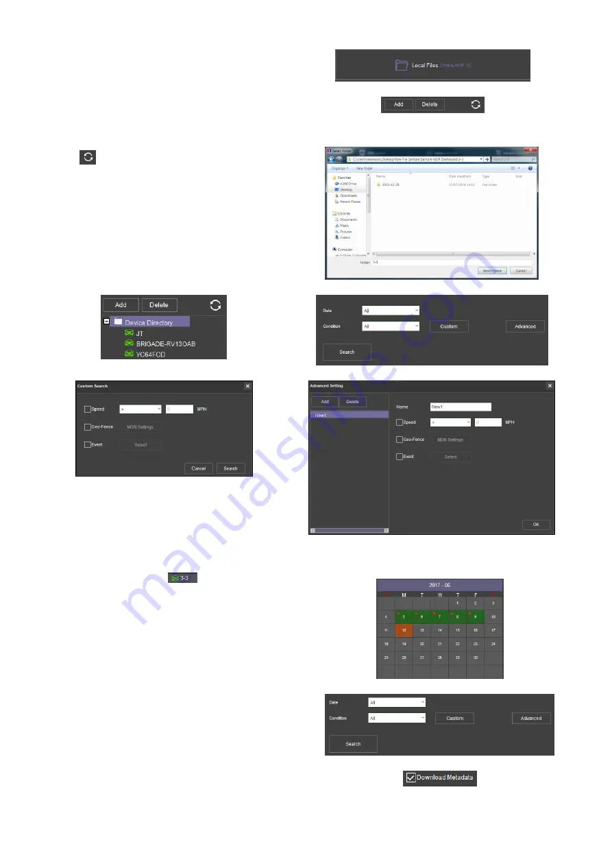
Users click on the
DIRECTORY
tab as shown in
•
Click the
ADD
button as shown in
Browse to the relevant folder and click
SELECT FOLDER
.
•
This brings up a Windows™ Explorer dialogue box
(
Windows Explorer Folder Figure 170
) which allows users to
select the folder that contains the recordings. Select the
MDR Vehicle name, in this example 3-3.
•
Once the folder has been successfully loaded, it will appear
as shown in
Directory Tab Figure 168
Directory Add Figure 169
•
If there was a directory specified previously, click the refresh
icon
to get the directory to appear. This will be a green
icon to indicate it is available for browsing.
•
Double-click the vehicle icon. This will display
ALL
calendar
events. A typical example of a calendar is shown in HDD
Calendar Figure 175
•
The directory will now appear in the left pane as shown in
•
Multiple directories can be specified. Directories may be
searched. See Directory Search Figure 172. Custom and
Advanced searches can be configured. See Windows
Explorer Folder Figure 170 and
Windows Explorer Folder Figure 170
Device Directory Figure 171
Directory Search Figure 172
Custom Search Figure 173
Advanced Search Settings Figure 174
9.8
Reading Data
•
Double-click the vehicle icon
. This will display ALL
calendar events.
•
Each colour represents:
➢
Green dates represent normal recordings
➢
Orange dates represent alarm recordings
➢
Red dots represent metadata data
➢
Blue outline represents
the current date (today’s date)
•
A typical example of a calendar is shown in
HDD Calendar Figure 175
•
To refine the data displayed, users should setup the search
criteria. Custom and Advanced searches can be created.
•
Ensure that the
DOWNLOAD METADATA
is always ticked. See
. This will ensure that all metadata
(graphical) is shown with playback video.
•
Users double-click on the relevant calendar date. This will then
display the pre-playback screen. See
Users can choose which channels to view during playback.
HDD Search Figure 176
Metadata Setting Figure 177
Summary of Contents for MDR-504-500
Page 9: ...9 3 5 MDR 504xx 500 Connection Diagram MDR 504xx 500 Connection Diagram Figure 8...
Page 10: ...10 3 6 MDR 508xx 1000 Connection Diagram MDR 508xx 1000 Connection Diagram Figure 9...
Page 89: ...89...
Page 90: ...90...
Page 91: ...91...
Page 92: ...92 18 10 2017 10 52 00 MDR 500 Series Installation Operation Guide v2 0 ENG 5145A docx...


