43
9.6.4
Sensor Status
•
The 2-character names are set in the OSD menu where
users name each sensor. See 7.3.1.1 IO for more
information.
•
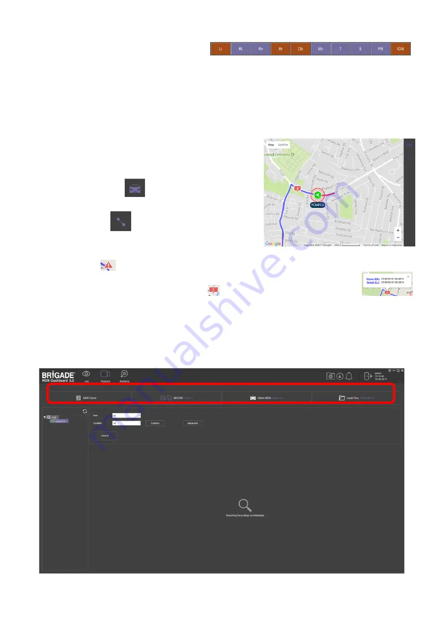
MDR-Dashboard 5.0 displays the status of the sensor
triggers at the bottom of the Frame Info (area 6).
shows the ignition (IGN) and the
sensor input named Br (Brake) triggered.
•
PB (Panic button) and IGN (Ignition) are not
configurable.
•
By default, your MDR has been set up to show Li (Left
Indicator), Ri (Right Indicator), Rv (Reverse camera)
and BR (Brake) sensors in the Frame Information.
Sensor Status Figure 165
9.6.5
Map Tracking
The map (area 5) refreshes the position of the vehicle continuously during
playback and displays the vehicle registration. Zooming in and out on the map
can be done using the +/- buttons.
•
There are two map view settings that can be turned on/off:
•
Lock map to vehicle automatically
•
Show Line/Hide Line
•
Click the Lock Map button
to ensure that the vehicle is always
shown in the centre of the map. If this is turned off then the map can move
freely regardless of the vehicle position.
•
Click the Line button
which will turn the vehicle route track line on
or off depending on this setting. It is advised to have this turned on.
•
The red trace indicates the route that has been travelled while the blue
represents the route the vehicle will travel. Google Maps Satellite View is
also supported.
Map Tracking Figure 166
•
A hazard symbol
on the map will show points where an alarm was triggered. If there are multiple alarms in close succession, a box
indicating the number of alarms will be shown on the map
. Click on these icons to access additional information
about the alarm.
•
Video playback will move to the event point if this is clicked on.
Note: As an alternative, MS Bing maps can be chosen. Changing maps requires restarting the MDR-Player 5.0 which will be requested
once the setting has been changed.
9.7
Loading from a USB flash drive or Folder
This procedure applies to recordings previously downloaded from the MDR and saved onto a USB flash drive or saved onto a PC.
•
To read exported files, click on the Directory tab found on the Data Source Access (area 1). See
Data Source Figure 167
1
Summary of Contents for MDR-504-500
Page 9: ...9 3 5 MDR 504xx 500 Connection Diagram MDR 504xx 500 Connection Diagram Figure 8...
Page 10: ...10 3 6 MDR 508xx 1000 Connection Diagram MDR 508xx 1000 Connection Diagram Figure 9...
Page 89: ...89...
Page 90: ...90...
Page 91: ...91...
Page 92: ...92 18 10 2017 10 52 00 MDR 500 Series Installation Operation Guide v2 0 ENG 5145A docx...


