25
Treadwall M6 Pro-V Owner’s Manual—2018
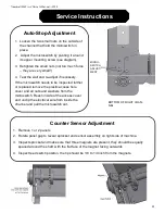
Service Instructions
MICRO-
SWITCH
ADJUST-
MENT
BOTTOM OF RIGHT CHAN-
NEL
Auto-Stop Adjustment
1. Loosen the two small nuts on the outside of
the channel that hold the microswitch in
place.
2. Adjust the microswitch by pivoting it around
its upper mounting screw (see diagram).
3. Retighten the small nuts (not too much force
– they are very small!)
4. Test the wall and re-adjust if necessary.
If the microswitch needs to be inspected further
or replaced remove the plastic access hole
cover and all nuts and washers from the
microswitch. Reach inside of the access cover
and unclip the electrical wire from inside the
channel and pull the microswitch out.
Counter Sensor Adjustment
1. Remove 1 or 2 panels
2. Rotate panel gap to reveal sprocket and sensor assembly on right side of machine.
3. Inspect sprocket and make sure that three magnets are present, they should be equally
spaced around the shaft with the flat face of the magnet facing outwards
4. Inspect reed switch position, the tip should be 1/8 to 1/4 inch from the magnets.

