BRAINTECH FM1000 series User Manual Download Page 28


28


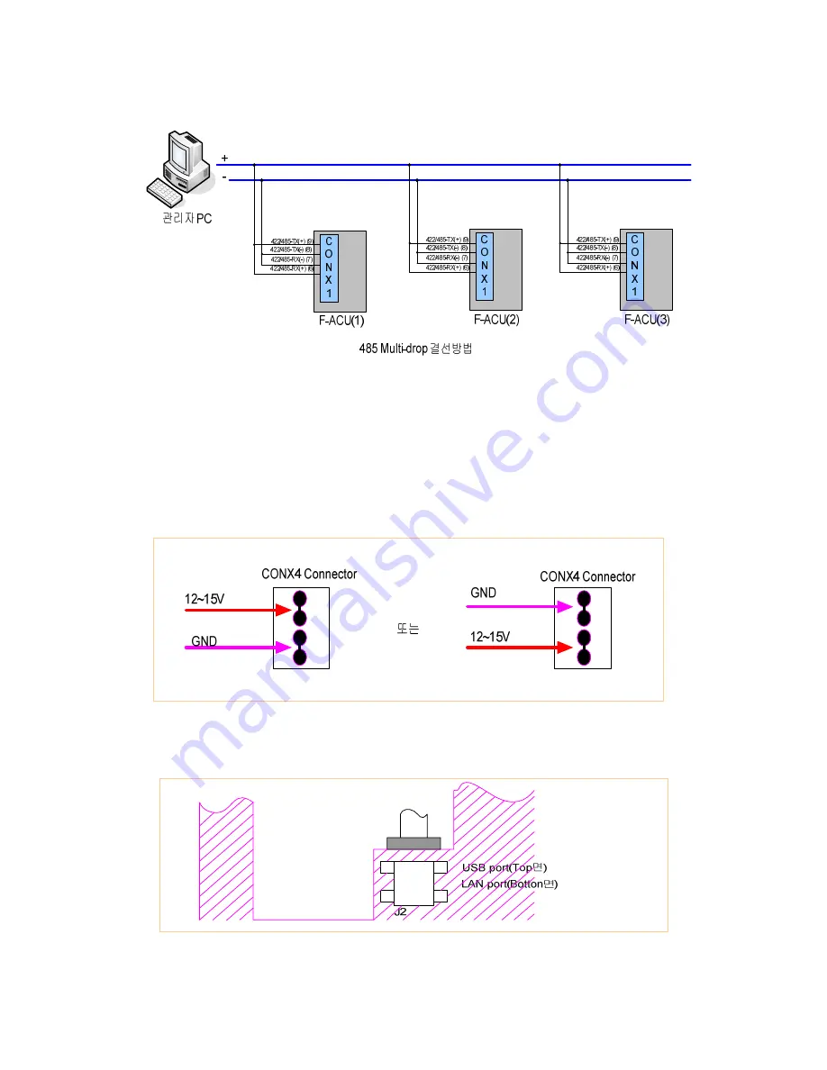
When it connect to 422/485 port, termination (JP10/JP11) needs to be connected to both 
ending points depend on the methods of connection.    If the case of administrator’s PC is 
one end point and F-ACU is another end point like above figure, administrator’s PC is to 
be terminated and do the termination only at F-ACU(3).    Just in case to connect to 485, 
it needs to be terminated one of JP10/JP11. 


11.2.3 Power Cable Connection 

☺  Connect DC power supply 12~15 V to Conx4 regardless of direction 


11.2.4 LAN Cable Connection   

☺  Connect to RJ-45 connector under J2 port 


Summary of Contents for FM1000 series

Page 1: ...User Manual Access Control Unit Model FM1000series Manufcture Brain Tech Co Ltd Sale Technical support Fingcas Corp ...

Page 2: ... 5 Entrance Exit Setup 6 DB Management 6 1 Setup Initialization 6 2 Event Initialization 7 Revision on Manager Password 8 Door Operation Open Close Setup 9 Usage by Entrance Exit Method 9 1 In case of fingerprint use 9 2 In case of card use 9 3 In case of password use 9 4 In case of card password use 9 5 In case of card fingerprint use 9 6 In case of fingerprint password use 9 7 In case of card pa...

Page 3: ... can be damaged if you arbitrarily open close or repair it Make sure to call the sales company or operator if needed 1 2 Product pacing and contents a Fingerprint In Out Control device 1 ea b Connector 11p 9p 4p 3 ea c Screw 2 type 5 ea d Basic software of In Out Control System and User Manual CD 1 ea e RF Card 3 ea Optional Item Sales product by order AC Power Adapter DC 12V 2 5A 1 3 Parts name a...

Page 4: ...ed menu The screen displays the selected menu Attendance The screen is in attendance mode Leaving Office The screen is in leaving office mode Go Out The screen is in go out mode Return Office The screen is in return office mode 1 4 2 Explanation of Key function Number 0 9 button The button is used when keying in a number and selecting a menu BAK button The button is used when canceling a number EN...

Page 5: ... fingerprint recognizer as shown in Picture 2 2 Manager Registration The manager password is not registered when you open the package box and operate the product for the first time No Register Master Password Please type Password Back NEXT F1 Cancel F4 Ok 1 When the power is on for the first time a window for setting the manager password will pop up as shown in the left screen No Register Master P...

Page 6: ...gement 4 Passwd change 5 Door Operation F1 Cancel F4 OK 1 Enter into the Controller Setup menu by pressing the number key 1 from the manager menu window on the left Controller Setup 1 Date Time 2 Network Setup 3 Manage Mode 4 ETC Setup 5 Door Setup F1 Cancel F4 OK 2 Select the date and time setup items by pressing the number key 1 from the Controller Setup menu Date Time Setting Year Month Day _ H...

Page 7: ...n the cursor will automatically move to the date blank 5 If you press the number key 8 to enter the date and press the button the cursor will move to the time blank 6 If you press the number key 9 to enter the time and press the button the cursor will move to the minute blank 7 After pressing the number keys 3 7 to enter the minute the cursor will automatically move to the second blank 8 After pre...

Page 8: ...screen OK ACU Number Successfully Changed 7 If you entered a number within the range of 001 to 255 you can confirm the successfully revised ACU Number from the left side screen Network Setup 1 ACU Number 2 Network Mode 3 LAN Setup 4 WL LAN Setup 5 UART Speed F1 Cancel F4 OK 8 After the ACU Number is entered the screen goes back to the Network Setup Screen If you press F4 from the left side screen ...

Page 9: ...e you want and pressing F4 button the Network Mode will be saved and the screen will go back to the Network Setup screen Refer to the terminology guideline to be informed of the Network Mode Network Setup Changed Restarting Wait a moment 6 If you press F4 button from the Network Setup screen the left side screen appears and the equipment will restart 4 3 1 LAN Setup MAIN Menu 1 Controller Setup 2 ...

Page 10: ...Cancel F4 OK 6 Use the number keys to enter the new IP address Use the button to enter in the middle of the numbers Curr Network 1 I P 199 000 000 000 2 GW 192 168 000 001 3 SM 255 255 255 000 4 DNS000 000 000 000 1 4 EDIT address F1 Cancel F4 OK 7 After finishing the input and pressing F4 button the input will be completed and the screen will go back to the Network Setup screen If you don t enter...

Page 11: ...save UART Speed the setup of UART Speed will be completed Network Setup Changed Restarting Wait a moment 6 If you press F4 to save the revised UART Speed the equipment will restart to apply the revised setup 4 4 Manager Mode Setup 4 4 1 Network Stand alone setup MAIN Menu 1 Controller Setup 2 User Management 3 DB Management 4 Passwd change 5 Door Operation F1 Cancel F4 OK 1 Press the number key 1 ...

Page 12: ... 4 4 4 LED Setup Set up the LED movements of the button ETC Setup 1 Beep Setup 2 Voice Setup 3 LED Setup 4 Comm Security F1 Cancel F4 OK 1 Press 3 from ETC Setup screen to select the LED Setup menu ETC Setup 1 Beep Setup 2 Voice Setup 3 LED Setup 4 Comm Security F1 Cancel F4 OK 1 Press 2 from ETC Setup screen to select the Voice Setup menu Voice Mode 1 Voice MAX 2 Voice MID 3 Voice LOW 4 Voice OFF...

Page 13: ... you want to control FTP TELNET ON OFF 1 FTP TELNET ON 2 FTP TELNET OFF CUR FTP TELNET ON F1 Cancel F4 OK 3 If you select FTP TELNET item you can see the left side screen After pressing the number key to set up FTP TELNET and pressing F4 the set up will be saved and you will go back to the previous screen ENC KEY Setup 1 KEY1 0 2 KEY2 0 3 KEY3 0 F1 Cancel F4 OK 4 If you press 2 from the COMM Secur...

Page 14: ...el F4 OK 3 You can set up the door operation After entering the item you want and pressing F4 to save the time you will go back to the previous screen Time will be set up in seconds Reference Hold Time Meaning that the door is opened Alarm Time Setting up the alarm ringing time 5 User Management 5 1 User Addition MAIN Menu 1 Controller Setup 2 User Management 3 DB Management 4 Passwd change 5 Door...

Page 15: ...USR 3 Passwd2 _ 4 StartDate 061013 5 End Date 321231 FP N RF 00000000 1 5 Finger F4 OK 5 Presses number key 3 and re input user password In case of input other number different with number inputting at Passwd1 error message should be registered and input again 1 ID 01234 0 USR 2 Passwd1 3 Passwd2 4 StartDate _ 5 End Date 321231 FP N RF 00000000 1 5 Finger F4 OK 6 Can input ready time to apply user...

Page 16: ...t and user information is saved After save screen returns by user management menu 5 2 User Deletion MAIN Menu 1 Controller Setup 2 User Management 3 DB Management 4 Passwd change 5 Door Operation F1 Cancel F4 OK 1 In administrator menu screen such as left press number key 2 and enter to User Management menu User Manager 1 Add User 2 Delete One User 3 Delete All User 4 Check User 5 Pass Method F1 C...

Page 17: ...inistrator menu screen such as left and enter to User Management menu User Manager 1 Add User 2 Delete One User 3 Delete All User 4 Check User 5 Pass Method F1 Cancel F4 OK 2 Press 4 in User Manager menu and select Check User article USER ID Date FP RF 0 9 search by ID search by Finger RF search by Card F1 Cancel F4 OK 3 If input user ID using number key relevant user s information is registered I...

Page 18: ...e exit and entrance method by pressing 3 5 is registered to available method PIN Exit and entrance by ID and password Card Exit and entrance by RF card Finger Exit and entrance with registered fingerprint 1 Method for USER 2 Group 1 Single 3 PIN Only 4 Card Only 5 Finger Only Press 1 5 for toggle F1 Cancel F4 OK 6 After completion of setting press F4 button to save setting and to return to previou...

Page 19: ...r Please Touch Finger 7 Taking in and out is possible by fingerprint and password Screen such as left is registered if press button and input fingerprint to fingerprint reader that has registered beforehand Need Password check _ Back Next F1 Cancel F4 OK 8 Can input password after input fingerprint If input correctly set password and press F4 then the door opens Caution Registered exit and entranc...

Page 20: ...vent article Init Event 1 Yes 2 No 3 if press 1 in left screen event is initialized and returns to previous screen Can return to previous screen without initializing setting if press 2 7 Revision of Manager Password MAIN Menu 1 Controller Setup 2 User Management 3 DB Management 4 Passwd change 5 Door Operation F1 Cancel F4 OK 1 Press number key 4 in administrator menu screen such as left and enter...

Page 21: ...trator menu screen such as left press number key 5 and returnss to Door Operation menu Door Mode Setup 1 Normal Mode 2 Close 3 Open 4 Schedule Close 5 Schedule Open Normal F1 Cancel F4 OK 2 Select wanted mode using number key 1 5 Normal Mode Normalcy mode Close Always closed Open Always opened Schedule Close Closed at specifying time Schedule Open Opened at specifying time Schedule Open S Y 1970 M...

Page 22: ...gerprint reader 14 Oct 2006 21 37 44 Thank You 2 when input right fingerprint screen such as left is registered and the door is opened with guidance sound of Ok You can pass 14 Oct 2006 21 37 44 No Trespassing 3 In case of input wrong fingerprint or do not input fingerprint within 5 seconds screens such as left is registered and comes out guidance sound of Please Contact your security Manager 9 2 ...

Page 23: ...press number button in initial screen there appears screen to be input user ID and password as like left Enter ID Password User ID 012 Password _ Back NEXT F1 Cancel F4 OK 2 If press button after input registered user ID using number key can input password Enter ID Password User ID 012 Password Back NEXT F1 Cancel F4 OK 3 If press F4 after input user password the door opens In case of input wrong ...

Page 24: ...ode 10 1 Attendance Mode select Attendance mode pressing F1 key 22 Oct 2006 12 11 11 Attendance 1 Select Attendance Mode pressing F1 key After selection input card fingerprint password card fingerprint password input refer to previous page 14 Oct 2006 21 37 44 Thank You 2 When Attendance mode operates normal screen such as left is registered When registered only fingerprint Input fingerprint press...

Page 25: ...lection Card fingerprint password input refer to previous page 14 Oct 2006 21 37 44 Thank You 2 When Go Out mode operates normal screen such as left is registered Occasion that only fingerprint is registered Input fingerprint pressing key after press F3 key 14 Oct 2006 21 37 44 No Trespassing 3 Input of Card fingerprint password are wrong error message such as left is registered 10 4 Return Office...

Page 26: ...Open Decide COM of Lock whether will open or connect on GND Close Lock_COM GND Jp125 1번2번 Alarm_Nc Decide Nc or Nc connection according to Lock type 2번3번 Alarm_No Jp126 1번2번 Jumping Lock_Nc Decide Nc or Nc connection according to Lock type 2번3번 Jumping Lock_No Jp3 ON Pass under Voltage Lock Counter electromotive force interception that was produced at Lock On Off Jp2 ON Pass under Voltage Alarm Co...

Page 27: ...g to LOCK type Door open sensor Connect with Dr Open 5 and GND 6 of Conx1 connector There is occasion that Lock and Door open sensor are together according to Door Alram Connect with alarm no nc 10 and Fuse 12 V 11 of Conx1 Do jumping JP126 according to alarm type CONX3 1 2 3 4 5 6 7 8 9 10 11 GND INPUT1 INPUT2 EXIT DOOR OPEN GND DOOR COM DOOR NO NC ALARM COM ALARM NO NC FUSED 12V 11 2 2 422 485 M...

Page 28: ...ne end point and F ACU is another end point like above figure administrator s PC is to be terminated and do the termination only at F ACU 3 Just in case to connect to 485 it needs to be terminated one of JP10 JP11 11 2 3 Power Cable Connection Connect DC power supply 12 15 V to Conx4 regardless of direction 11 2 4 LAN Cable Connection Connect to RJ 45 connector under J2 port ...

Page 29: ...n key back lighting Memory 16MB RAM 16Mb flash Memory 2MB boot ROM CPU 32 Bit RISC CPU Signal Interface 2 Output lock alarm etc 4 Input door lock status Wiegand Output System Software Access Control and Time Attendance Operating Environment 20 50 C Lower than 90 RH Non Condensing RF Reader Bulit in 125 KHz RF reader or 13 56 MHz RF reader Dimensions Unit mm 125 W x 163 H x 48 D Weight 430g 11 4 Ch...

Page 30: ...uctions may cause harmful interference to radio communications However there is no guarantee that interference will not occur in a particular installation If this equipment does cause harmful interference to radio or television reception which can be determined by turning the equipment off and on the user is encouraged to try to correct the interference by one or more of the following measures Reo...

Reviews: