5
Physical Features
1.
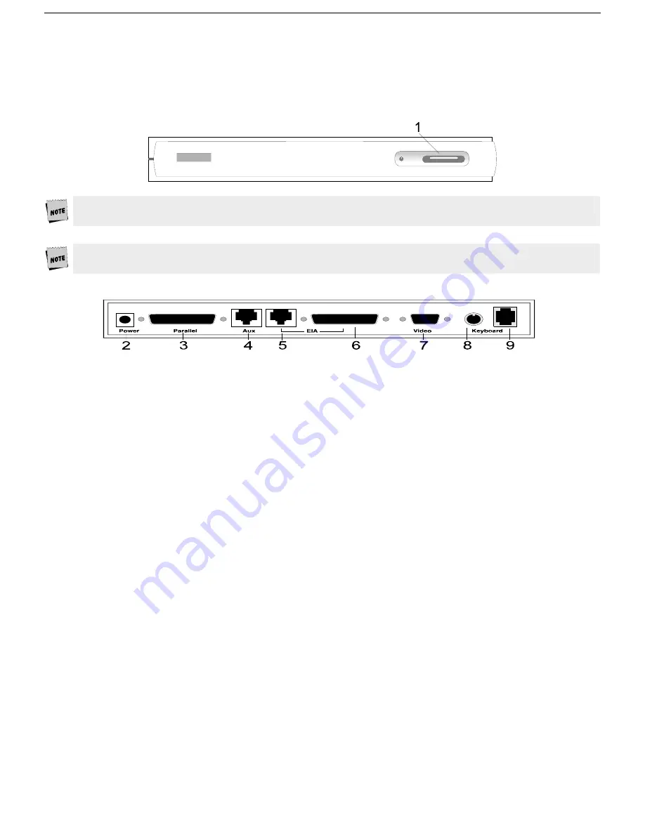
Power Switch
- press the orange button to its recessed position to turn the unit “on.” Press again to turn
the unit “off.”
Leave the terminal’s power switch (1) in the off position “0" until power and keyboard connections are made
The Canadian Standards Association (CSA) recommends that the power outlet be near the terminal and easily
accessible at all times.
2.
Power Connection
- plug the power cord into this connector and the wall-mount or other remote
transformer into a properly grounded receptacle.
3.
Parallel Printer Port
- connect the cable from the IBM or Centronics compatible parallel printer to this port.
See Chapter 2 for installation options.
4.
Host/Printer Port 2 (RJ45)
- labeled “Aux” - with an RJ45 connector only, connect the cable from a second
host (dual host mode) or serial printer here. See Chapter 2 for installation options.
5.
Host/Printer Port 1 (RJ45)
- labeled “EIA” - with a RJ45 connector only, connect the cable from the first
host or serial printer here. Connect only one EIA port at a time. See Chapter 2 for installation options.
6.
Host/Printer Port 1 (DB25)
- labeled “EIA” - with a DB25 connector only, connect the cable from the first
host or serial printer here. Connect only one EIA port at a time. See Chapter 2 for installation options.
7.
Video - Output to monitor
- attach the connector from the monitor here. The port is a DB15 female which
means that a DB15 male connector is required.
8.
Keyboard Connector (mini-din)
- on a Compact PC 101-key keyboard only, line up the notch and pins of
the mini-din connector and push in here. Connect only one keyboard at a time.
9.
Keyboard Connector (RJ11)
- on a PC(101/102) or ANSI keyboard, push in the keyboard connector here.
Connect only one keyboard at a time.


