background image

AutoDome Easy IP

Settings Menus | en

99

Bosch Security Systems, Inc.

Installation Manual

F01U079609 | 1.0 | 2008.08

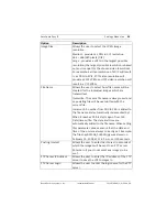
Option Description

Image Size

Allows the user to select the JPEG image 
resolution.
Medium - provides a JPEG in CIF resolution 
352 × 288/240 pixels (CIF)
Large - provides a JPEG in the largest possible 
resolution (the largest possible resolution is based 
on (and is equal to) the chosen video resolution). 
For example, a video resolution of 4CIF will result 
in a JPEG in 4CIF, 2CIF video resolution will 
provide a 2CIF JPEG, and CIF video resolution will 
result in a CIF JPEG.

File Name

Allows the user to select how file names will be 
created for the individual images which are 
transmitted. 
Overwrite: The same file name is always used and 
any existing file will be overwritten with the 
current file.
Increment: A number from 000 to 255 is added to 
the file name and automatically incremented by 1. 
When it reaches 255 it starts again from 000. 
Date/time suffix: The date and time are 
automatically added to the file name. When setting 
this parameter, please ensure that the date and 
time of the unit are always correctly set. Example: 
the file snap021606_124530.jpg was stored on 
February 16, 2006 at 12.45 p.m. and 30 seconds.

Posting Interval

Allows the user to enter the interval in seconds at 
which the images will be sent to an FTP server. 
Enter zero if you do not want any images to be 
sent. 

FTP Server IP Address

Allows the user to enter the IP address of the FTP 
server to save the JPEG images to. 

FTP Server Login

Allows the user to enter the login name for the FTP 
server. 

Summary of Contents for VEZ IP Series

Page 1: ...AutoDome Easy IP VEZ IP Series en Installation Manual ...

Page 2: ......

Page 3: ...ts List 13 2 2 Additional Tools Required 13 2 3 Safety Rules 14 3 Description 15 4 Preparing the Wiring 17 4 1 Ethernet control and video 17 4 2 Power 17 4 3 Alarm 18 5 Connections 19 5 1 Connecting to the Ethernet 19 5 2 Connecting the Power 19 5 3 Connecting the Alarm Input 20 6 Mounting Installation 21 6 1 Installing the Wall Mount 21 6 2 Installing the Pipe Mount 25 6 2 1 Installing the Base t...

Page 4: ...wing Live Images and Controlling the PTZ 45 9 1 Establishing a Connection 45 9 2 Configuring Data Streams 45 9 3 Controlling Camera Operations 46 9 4 Entering a Keyboard Control Command 49 10 Navigating the Menus 53 10 1 Preset Menu 54 10 1 1 Setting and Saving Presets 55 10 1 2 Recalling a Preset Position 56 10 1 3 Creating Titles 56 10 2 Tour Menu 57 10 2 1 Setting a Tour 58 10 2 2 Running Stopp...

Page 5: ...creenshot 83 12 Settings Menus 85 12 1 General Main Menu 85 12 1 1 Identification Menu 86 12 1 2 Display Stamping Menu 86 12 1 3 Password Menu 88 12 1 4 Language Menu 89 12 1 5 Date Time Menu 89 12 1 6 Time Server Menu 90 12 2 Encoder Main Menu 93 12 2 1 Picture Settings Menu 94 12 2 2 Encoder Profile Menu 94 12 2 3 Profile Configuration 95 12 2 4 JPEG Posting Menu 98 12 3 Recording Main Menu 100 ...

Page 6: ...ing 119 12 8 5 Recording Status 119 12 9 Alarm Menu 119 12 9 1 Alarm Sources 120 12 9 2 Alarm Connections 120 12 9 3 Sending an Alarm E mail 122 12 10 Service Main Menu 123 12 10 1 Network Menu 123 12 10 2 Multicasting 125 12 10 3 Encryption 126 12 10 4 Version Information 128 12 10 5 Livepage Configuration 128 12 10 6 Licenses 130 12 10 7 Maintenance 130 13 Keyboard Commands by Number 133 14 Prev...

Page 7: ... and ensure reliable operation Do not block or cover these openings Do not place the unit in an enclosure unless proper ventilation is provided or the manufacturer s instructions have been adhered to 4 Water Do not use this unit near water for example near a bathtub washbowl sink laundry basket in a damp or wet basement near a swimming pool in an outdoor installation or in any area classified as a...

Page 8: ...e latest versions of IEC Publication 227 or IEC Publication 245 10 Power disconnect Units with or without ON OFF switches have power supplied whenever the power cord is inserted into the power source however the unit is operational only when the ON OFF switch is in the ON position The power cord is the main power disconnect device for switching off the voltage for all units 11 Power sources Operat...

Page 9: ...pment an object has fallen into the unit the unit has been dropped or the unit cabinet is damaged the unit exhibits a distinct change in performance the unit does not operate normally when the user correctly follows the operating instructions 14 Replacement parts Be sure the service technician uses replacement parts specified by the manufacturer or that they have the same characteristics as the or...

Page 10: ...itch Incorporate an all pole power switch with a contact separation of at least 3 mm in each pole into the electrical installation of the building If it is needed to open the housing for servicing and or other activities use this all pole DANGER DANGER High risk This symbol indicates an imminently hazardous situation such as Dangerous Voltage inside the product If not avoided this will result in a...

Page 11: ... with NEC800 CEC Section 60 Coax grounding Ground the cable system if connecting an outside cable system to the unit Connect outdoor equipment to the unit s inputs only after this unit has had its grounding plug connected to a grounded outlet or its ground terminal is properly connected to a ground source Disconnect the unit s input connectors from outdoor equipment before disconnecting the ground...

Page 12: ...You must wear grounded wrist straps and observe proper ESD safety precautions when handling the electrostatic sensitive printed circuit boards Fuse rating For security protection of the device the branch circuit protection must be secured with a maximum fuse rating of 16 A This must be in accordance with NEC800 CEC Section 60 Grounding and polarization This unit may be fitted with a polarized alte...

Page 13: ...e it might come into contact with power lines circuits or lights SELV All the input output ports are Safety Extra Low Voltage SELV circuits SELV circuits should only be connected to other SELV circuits Because the ISDN circuits are treated like telephone network voltage avoid connecting the SELV circuit to the Telephone Network Voltage TNV circuits Video loss Video loss is inherent to digital vide...

Page 14: ...nce to radio communications Operation of this equipment in a residential area is likely to cause harmful interference in which case the user will be required to correct the interference at his expense Intentional or unintentional modifications not expressly approved by the party responsible for compliance shall not be made Any such modifications could void the user s authority to operate the equip...

Page 15: ...entielle peut provoquer des interférences nuisibles Le cas échéant l utilisateur devra remédier à ces interférences à ses propres frais Au besoin l utilisateur consultera son revendeur ou un technicien qualifié en radio télévision qui procédera à une opération corrective La brochure suivante publiée par la Commission fédérale des communications FCC peut s avérer utile How to Identify and Resolve R...

Page 16: ...sch Security Systems Inc and is protected by copyright All rights reserved Trademarks All hardware and software product names used in this document are likely to be registered trademarks and must be treated accordingly i NOTICE This user guide has been compiled with great care and the information it contains has been thoroughly verified The text was complete and correct at the time of printing The...

Page 17: ...phone 888 289 0096 Fax 585 223 9180 E mail security sales us bosch com Technical Support Telephone 800 326 1450 Fax 585 223 3508 or 717 735 6560 E mail technical support us bosch com Repair Center Telephone 585 421 4220 Fax 585 223 9180 or 717 735 6561 E mail security repair us bosch com Canada Telephone 514 738 2434 Fax 514 738 8480 Europe Middle East Asia Pacific Region Telephone 44 0 1495 27455...

Page 18: ...12 en Safety AutoDome Easy IP F01U079609 1 0 2008 08 Installation Manual Bosch Security Systems Inc ...

Page 19: ...tems Sales or Customer Service Representative The original packing carton is the safest container in which to transport the unit and must be used if returning the unit for service Save it for possible future use 2 1 Parts List The AutoDome Easy IP includes the following components One 1 PTZ Dome dome camera One 1 accessory kit including One 1 locking torx wrench T 10 One 1 locking torx wrench T 20...

Page 20: ...e to a power source corresponding to the indications given on the marking label Use only the attachments accessories specified by the manufacturer Unplug the device during lightning storms or when unused for long periods of time Do not use the device near water Do not use the device in the presence of inflammable substances Do not allow children or unauthorized personnel to use the device Do not b...

Page 21: ...AutoDome Easy IP Unpacking en 15 Bosch Security Systems Inc Installation Manual F01U079609 1 0 2008 08 ...

Page 22: ...building blocks for this surveillance security system By using multiple on screen keyboard controllers and multiple dome cameras no place is too large for monitoring Extensible and flexible architecture facilitates remote control functions via a web browser or DVR see Figure 3 1 for a sample configuration Figure 3 1 System configuration Description 1 Power supply 2 PC 3 Ethernet over CAT 5E or CAT...

Page 23: ...AutoDome Easy IP Description en 17 Bosch Security Systems Inc Installation Manual F01U079609 1 0 2008 08 ...

Page 24: ... a CAT 5E Ethernet cable terminated with an RJ45 female connector 4 2 Power The recommended power cable is a 2 conductor 14 18 gage cable depending on the distance Refer to the wiring distance guide below Power connections Follow the instructions in the table below to terminate the two 2 power connections CAUTION Installation should only be performed by qualified service personnel in accordance wi...

Page 25: ...ance Refer to the wiring distance guide below Alarm connections Follow the instructions in the table below to terminate the two 2 alarm connections Wire color Description 24 VAC operation 12 VDC operation Red AC positive DC positive Orange AC negative DC negative DC common or ground Wire size Maximum distance AWG mm feet meters 22 0 644 500 152 4 18 1 024 800 243 8 Wire color Description Blue Alar...

Page 26: ...ange lead to the negative DC common or ground power input lead If you are connecting the unit to a 24 VAC power input the connection of the leads does not matter To connect the power do the following 1 Locate the cable assembly with a two 2 pin mating connector on one end and the red and orange flying leads on the other end 2 If connecting to the 12 VDC power input a Connect the positive red lead ...

Page 27: ...nnection with a receiving device and send an alarm e mail The default alarm state is normally open but may be programmed to be normally closed To connect the alarm input do the following 1 Locate the cable assembly with a two 2 pin blue mating connector on one end and the blue and violet flying leads on the other end 2 Connect the ground of the alarm source dry contact to the blue wire alarm commo...

Page 28: ...g wall mount supplied separately 6 1 Installing the Wall Mount 1 Determine a secure location for the wall mount supplied separately 2 Fit a user provided metal single gang junction box to the wall 3 Attach a grounded metal conduit to the junction box clamp Figure 6 1 Metal conduit 4 Feed the wires through the conduit 5 Feed all wires from the metal junction box through the arm 6 Attach the mountin...

Page 29: ... 2 Fit to gang junction box 8 Secure with the appropriate user provided SEMS screws that have an integral lock washer to dig through the paint and ensure an electrical ground connection to the arm housing i NOTICE The metal junction box and mounting surface must be capable of supporting a maximum load of 11 33 kg 25 pounds ...

Page 30: ...l 9 Attach the mounting plate supplied with dome to the dome mounting cap with the three 3 screws supplied Ensure that the mounting plate s front end as labeled on the plate is screwed into the threaded stud furthest away from the wall 180 degrees as shown in Figure 6 4 Figure 6 4 Attaching the mounting plate to the dome cap Number Description 1 Arm 2 Cap ...

Page 31: ...sitioned between the mounting plate and the dome mounting cap Figure 6 5 Attaching the safety wire to the mounting plate 12 Attach the camera to the mounting plate by inserting the vertical tab into the recessed slot on the top of the camera dome to the right of the safety locking screw Rotate the camera approximately 15 degrees to the right and lock into place as shown in the illustration below N...

Page 32: ...ly grounded 6 2 Installing the Pipe Mount 1 Identify a secure hard surface location for the ceiling pipe mount supplied separately 2 Use the four 4 holes in the flange as a template to mark the position where the holes should be drilled to secure the mount 3 Drill the four 4 holes in the installation location screws not supplied use a minimum of 10 mm 39 in 4 Drill a fifth hole maximum of 20 mm in...

Page 33: ... pipe and the pipe to the cap Note Select the pipe length of 20 cm 7 9 in 30 cm 11 8 in or combine the two 2 pipes with the integral coupler for 50 5 cm 20 in 7 Secure the flange using four 4 appropriate user provided fasteners such as Moly or Toggle bolts 8 Attach the grounded metal conduit Figure 6 8 Grounded metal conduit 9 Pull the wires from the pipe starting at the flange end ...

Page 34: ...ng cap with the three 3 screws supplied Ensure that the mounting plate s front end as labeled on the plate is screwed to the first front thread as shown in Section Figure 6 10 Attaching the mounting plate to the dome cap page 29 i NOTICE The fasteners and mounting surface must be capable of supporting a maximum load of 11 33 kg 25 pounds CAUTION Select a rigid mounting location to prevent excessiv...

Page 35: ...ounting plate to the dome cap 11 Attach the dome camera to the mounting plate using the safety wire 12 Connect all wires to the camera Ensure that the female RJ45 connector on the camera s cable assembly is positioned between the mounting plate and the dome mounting cap Number Description 1 Align front of plate here 2 Feed wires through here ...

Page 36: ...o the mounting plate 13 Attach the camera to the mounting plate by turning the dome camera approximately 15 degrees to the right and locking into place as shown in the illustration below Figure 6 12 Attaching the AutoDome Easy IP to the mounting plate 14 Secure the safety locking screw with the locking torx wrench T 10 supplied with the AutoDome Easy IP ...

Page 37: ...steps below 1 Carefully loosen the bubble by using the torx wrench provided to remove the four 4 tamper resistant screws Allow the bubble to hang from the safety tether 2 Remove the appropriate two 2 see Figure 6 13 black rubber plugs from the camera base Figure 6 13 Removing the plugs from the camera base 3 Connect the prepared wiring as described in Section 5 Connections matching the colors of t...

Page 38: ...ase the camera pans left and right and tilts up and down It also adjusts the lens focus The entire homing phase lasts approximately 40 seconds and displays the following splash screen throughout its homing phase START UP BOSCH Version 2 0 x i NOTICE The error message PROTOCOL IS NOT MATCHED is displayed during the power up cycle if switches 9 and 0 are not set to their correct factory default sett...

Page 39: ...AutoDome Easy IP Mounting Installation en 33 Bosch Security Systems Inc Installation Manual F01U079609 1 0 2008 08 ...

Page 40: ...ch the video standard of the camera model NTSC 60 Hz ON or PAL 50 Hz OFF Switches 9 and 0 set to Bosch protocol Figure 7 1 AutoDome Easy camera function and protocol selection switches Table 7 1 Dome camera function Table 7 2 Dome camera protocol function i NOTICE The error message PROTOCOL IS NOT MATCHED is displayed during the power up cycle if switches 9 and 0 are not set correctly Reference De...

Page 41: ...col and Video Format en 35 Bosch Security Systems Inc Installation Manual F01U079609 1 0 2008 08 i NOTICE Do not adjust the S W no 8 NTSC and PAL video standards The switch setting must agree with the video standard model purchased ...

Page 42: ... recorders The use of existing networks indicates that integration with CCTV systems or local networks can be achieved quickly and easily Video images from a single camera can be simultaneously received on several receivers 8 1 Overview of Features The IP module adds the following functionality to an AutoDome Easy system Function Description Video encoding The camera uses the H 264 MPEG 4 Part 10 ...

Page 43: ...ems Inc Installation Manual F01U079609 1 0 2008 08 Snapshots Allows you to take and store individual video images as JPEG files from the web browser interface Backup Saves video images as a file on a computer s hard drive from the web browser interface Function Description ...

Page 44: ...orer or any of the Bosch software the computer must conform to the following minimum requirements Processor 1 8 GHz Pentium IV RAM 256 MB Video system 128 MB video memory 1024x768 display with a minimum of 16 bit color Network interface 100 Base TX DirectX 9 0c available at www boschsecurity com Microsoft Internet Explorer version 6 0 or higher Java Virtual Machine available at www boschsecurity c...

Page 45: ...subnet an IP address belongs to Gateway IP address a node on a network that serves as an entrance to another network Port an endpoint to a logical connection in TCP IP and UDP networks The port number identifies the use of the port for use through a firewall connection The AutoDome Easy IP defaults are as follows IP address 192 168 0 1 Subnet mask 255 255 255 0 Gateway IP address 0 0 0 0 The follo...

Page 46: ... Software To view live video proceed as follows 1 Download the most recent version of all required software by going to www boschsecurity com When the homepage is displayed click on your location then select your country i NOTICE The AutoDome Easy IP can also be connected directly to a PC using an Ethernet crossover cable with RJ45 connectors see option B below A System configuration using a netwo...

Page 47: ...chsecurity com or the AutoDome Easy IP web server 8 6 1 Installing the Configuration Manager The Configuration Manager is an optional network utility that enables the user to set specific parameters for the AutoDome Easy IP To install the Configuration Manager software proceed as follows Download the Configuration Manager and NET Framework if required from www boschsecurity com and follow the on s...

Page 48: ... the appropriate unit IP address subnet mask and gateway address provided by your IT department Click OK when finished Figure 8 2 Network Settings dialog box 5 Re cycle power to the dome then click refresh on the Network tab 8 6 3 Using the AutoDome Easy IP Web Server The AutoDome Easy IP incorporates a network video server in the IP module To configure the camera using the AutoDome Easy IP web se...

Page 49: ...IP a security warning message is displayed 3 Check the Always Trust box then click YES If a security warning message window is not displayed you may need to manually add the IP address of the Autodome Easy IP to the list of trusted sites in the Security tab within the Tools Internet Options menu in Internet Explorer 4 Click the Settings link located at the top of the Livepage 5 Click the Service l...

Page 50: ... the original IP address followed by reset For AutoDome Easy IP use the new IP address to access the Livepage For example type http 192 168 0 1 reset in the address bar and click Go 11 Select RUN from the Windows Start menu and type arp d then click OK Figure 8 4 Run menu 12 Disconnect the AutoDome Easy IP Ethernet cable from the dedicated network switch and reconnect the Ethernet cable to the loc...

Page 51: ...AutoDome Easy IP Configuring IP Communications en 45 Bosch Security Systems Inc Installation Manual F01U079609 1 0 2008 08 ...

Page 52: ...me IP into the browser s address bar and click Go 3 If the AutoDome is password protected the system prompts you to enter a user name and password If for any reason you forget or need to change your password contact Technical Support 4 Type the user name and the associated password in the appropriate fields 5 Click OK to open the AutoDome Easy IP Livepage The Livepage displays the video image from...

Page 53: ...he different displays for the camera image Figure 9 1 H 264 streaming video 9 3 Controlling Camera Operations The View Control tab and the Aux Control tab allow you to control camera functions pan tilt zoom focus and iris navigate through on screen menus and view preset shots View Control tab The following figure illustrates the View Control tab and the actions that you can initiate from the tab ...

Page 54: ...he mouse scroll wheel while in the live video frame Number Description 1 Tilt the camera up 2 Tilt the camera down 3 Pan the camera to the left 4 Pan the camera to the right 5 Pan and tilt the camera in all directions 6 Zoom out1 7 Zoom in1 8 Focus far 9 Focus near 10 Iris closed 11 Iris open 12 Set preset shots 1 6 in conjunction with buttons 1 6 13 Move the camera to preset shot numbers 1 2 3 4 ...

Page 55: ...ra Digital I O The status of the alarm input is displayed in the Digital I O window If the alarm is active the LED symbol above Input 1 lights up Figure 9 3 Digital I O panel System and event logs The System Log field contains information about the operating status of the AutoDome Easy IP and the connection The Event Log field contains information about alarm conditions The following figure illust...

Page 56: ...mmand to the camera or displays an on screen menu Aux Control tab The Aux Control tab allows you to enter preprogrammed keyboard control commands See Chapter 13 Keyboard Commands by Number on page 133 for a list of all commands To access the Aux Control tab navigate to the Livepage and click the Aux Control tab The following figure illustrates this tab Figure 9 5 Aux Control tab Number Description...

Page 57: ... the memory for future use See Section 10 1 1 Setting and Saving Presets page 56 for more information 1 Click the View Control tab and use the on screen joystick to position the camera 2 Click and hold the mouse to pan to the desired position you want to save 3 Click any number combination from 1 60 from the on screen keypad to identify the scene number 4 Click the Set Shot button The image area d...

Page 58: ... Preset Position page 56 for more information 1 Click the number of the scene you want to view using the on screen keypad 2 Click the Show Shot button If you enter a shot number that has not yet been saved the image area displays the message DATA NOT PROGRAMMED WARNING For more information about the AutoDome Easy IP settings and controls click the link to open the AutoDome Easy IP online Help ...

Page 59: ...AutoDome Easy IP Viewing Live Images and Controlling the PTZ en 53 Bosch Security Systems Inc Installation Manual F01U079609 1 0 2008 08 ...

Page 60: ... view to be recalled Also known as preset shot Tour Accesses a sequence of preset shots that are combined to provide a preprogrammed tour of the area covered by an AutoDome Easy IP camera Auto pan Accesses a range of 1 4 for customized auto pan tours Sector Breaks the total 360 degrees into eight 8 sectors of 45 degrees each Individual titles may be assigned to each sector Alarm Accesses the alarm...

Page 61: ...4 5 6 7 8 9 0 3 1 2 3 4 5 6 7 8 9 0 CAMERA SETUP DOME SETUP 4 1 2 3 4 5 6 7 8 9 0 5 1 2 3 4 5 6 7 8 9 0 EXIT SAVE AND EXIT EXIT W O SAVE Menu item Description Number Accesses a range of 1 60 customized preset shots shots must be saved in sequence Title Controls a 10 character scene name that is displayed when the AutoDome Easy IP shows a preset shot must be user defined via the Title OSD See 10 1 ...

Page 62: ...PRESET SAVING If the user attempts to overwrite an existing preset shot the following confirmation message is displayed OVERWRITE CURRENT SCENE 10 1 2 Recalling a Preset Position The AutoDome Easy IP is designed to recall up to 60 preset locations To recall a preset position proceed as follows 1 Press the Aux Control tab 2 Press the desired screen shot 1 60 Show Shot The AutoDome Easy IP displays ...

Page 63: ...he appropriate preset position to which you want to assign a title Note A position must have been previously set in order for a title to be assigned See 10 1 1 Setting and Saving Presets to set a preset position 5 Press the down arrow to select TITLE then press the zoom in button two 2 times to begin access to characters A Z and numbers 0 9 The letter A is displayed and starts blinking indicating ...

Page 64: ...XIT EXIT EXIT W O SAVE Menu item Description Tour Accesses a sequence of preset shots that are combined to provide a preprogrammed tour of the area covered by an AutoDome Easy IP camera Title Controls a 10 character tour name that is displayed when the AutoDome Easy IP runs the preset tour must be user defined via the Title OSD See 10 1 3 Creating Titles Dwell time Allows a range of 05 99 SEC The ...

Page 65: ...ing Titles page 57 6 Press the down arrow to select the DWELL TIME field 7 Press the right arrow to increase the time or the left arrow to decrease the time 05 99 SEC 8 To set the sequence of preset shots press the down arrow on the on screen joystick to select the field then press the zoom in button once to access the numbers A number is displayed and the cursor starts blinking indicating that it...

Page 66: ...uously between right and left limit settings This menu provides access to the starting point ending point tilt and zoom and a customized title feature i NOTICE A shortcut is available for tour 1 Press 8 Aux On MAIN MENU AUTO PAN MENU PRESET AUTO PAN 1 TOUR TITLE AUTO PAN START POINT 017 0 SECTOR TILT AND ZOOM 002 6 ALARM END POINT 176 9 CAMERA SETUP SAVE AND EXIT DOME SETUP EXIT W O SAVE EXIT Menu...

Page 67: ...d to gain access of the CONTROL Toggle back to the View Control tab and use the on screen joystick to select the camera s pan starting point When finished toggle to the Aux Control tab and press 5 Aux Off 8 Press the down arrow via the on screen joystick to select TILT AND ZOOM 9 Press the Aux Control tab then press 5 Aux On via the on screen keypad to gain access of the CONTROL Toggle back to the...

Page 68: ...ay a customized auto pan between limits To run the auto pan feature proceed as follows 1 Press the Aux Control tab then press 3 0 auto pan number Show Shot via the on screen keypad For example to run the auto pan for course 4 press 3 0 4 Show Shot 2 To stop the auto pan toggle to the View Control tab and move the on screen joystick Note This is invalid if in Menu mode 10 4 Sector Menu The sector f...

Page 69: ...mized sectors 1 Title Controls a 10 character sector title that is displayed when the AutoDome Easy IP pans in any direction can also be user defined via the Title OSD SECTOR1 Start point Sets the left limit to display the sector title Sector 1 0 Sector 2 45 Sector 3 90 Sector 4 135 Sector 5 180 Sector 6 225 Sector 7 270 Sector 8 315 End point Sets the right limit to display the sector title Secto...

Page 70: ...eset shot when an alarm is activated Save and exit Saves the data and exits the menu Exit W O save Exits the menu without saving the data Menu item Description Default i NOTICE Sector titles are displayed any time the camera moves and disappear three 3 seconds after the camera stops MAIN MENU ALARM MENU PRESET INPUT NO TOUR OPTION LATCHED AUTO PAN PRESET 05 SECTOR DWELL TIME ALARM SAVE AND EXIT CA...

Page 71: ...rm activation the camera moves to the defined preset position and remains in Alarm mode until 65 Aux Off is pressed After the alarm is acknowledged the OSD text ALARM is removed and the PTZ control is re enabled Time Out Preset Moves to the defined preset upon alarm activation All saved presets are available 01 Dwell time In Time Out mode the camera remains in Alarm mode for the specified dwell ti...

Page 72: ...e down arrow on the on screen joystick with your mouse select ALARM then press the right arrow to display the menu options 4 When satisfied with your selections press the down arrow to select SAVE AND EXIT To exit without saving select EXIT W O SAVE 5 Exit the main menu 6 Press the Settings link within the AutoDome Easy IP web interface click the Alarm drop down list then press Alarm Sources 7 Cli...

Page 73: ...TOUR WB CONTROL AUTO PAN AE CONTROL SECTOR L L CONTROL ALARM PICTURE CAMERA SETUP INITIALIZE CAMERA DOME SETUP EXIT EXIT Menu item Description Focus control Controls the focus mode and digital zoom WB control Controls the white balance mode AE control Controls the auto exposure options L L control Selects between internal crystal and line lock external modes Picture Controls the mirror and sharpne...

Page 74: ...s again after a PTZ function is performed Auto after PTZ movement has stopped the camera focuses automatically until the camera achieves the desired focus 3 to 30 seconds depending on how much contrast is in the center of the scene The camera automatically performs the focus process again when any motion or change of any subject on the screen is detected or after a PTZ function is performed Manual...

Page 75: ...s to the white balance modes which include auto indoor outdoor and manual Save and exit Saves the data and exits the menu Exit W O save Exits the menu without saving the data Menu Description Options Default CAMERA SETUP MENU WB CONTROL MENU FOCUS CONTROL MODE AUTO WB CONTROL R GAIN AE CONTROL B GAIN L L CONTROL SAVE AND EXIT PICTURE EXIT W O SAVE INITIALIZE CAMERA EXIT ...

Page 76: ...s output color independent of the lighting used Auto Automatically adjusts the output color to display a natural color independent of the lighting used Auto R gain Adjusts the red gain to optimize the white point Available in Manual mode only Allows a range of 0 255 Automatic ally adjusts the camera to the current light level when in Manual mode B gain Adjusts the blue gain to optimize the white p...

Page 77: ...AE Control Menu The AE Control menu provides access to auto exposure options which include modes iris gain shutter and brightness CAMERA SETUP MENU AE CONTROL MENU FOCUS CONTROL MODE AUTO WB CONTROL IRIS AE CONTROL GAIN L L CONTROL SHUTTER PICTURE BRIGHT 30 INITIALIZE CAMERA BACK LIGHT OFF EXIT SAVE AND EXIT EXIT W O SAVE ...

Page 78: ...s the gain and shutter The iris and brightness may be predefined Manual The camera operates in Manual mode The iris gain and shutter must be predefined Flickerless The camera automatically removes flicker when camera signal format does not coincide with the power source frequency For example when an NTSC camera is used with 50 Hz power AUTO Iris Controls the lens s F stop value to manually adjust ...

Page 79: ...rless mode Bright Reduces the camera s iris level for proper exposure Allows a range of 0 90 30 Back light Selectively amplifies parts of the image to compensate for large contrast differences when only a portion of the image is brightly lit e g a person in a sunlit doorway ON OFF OFF Save and exit Saves the data and exits the menu Exit W O save Exits the menu Menu Description Options Default Mode...

Page 80: ...ower line when applying 24 VAC or when applying DC power External Synchronizes camera to AC power when applying 24 VAC power input This choice may improve white balance under certain lighting conditions Internal Phase Optimizes the line lock in multiphase power applications Allows a range of 0 620 PAL Allows a range of 0 519 NTSC Automatically adjusts to the AC power line Save and exit Saves the d...

Page 81: ...me information NOTE When setting the language it must be set in two 2 separate locations see 10 8 1 Setting the Language Menu Description Options Default Mirror Selects a mirror image ON OFF OFF Sharpness Adjusts the sharpness of the picture Allows a range of 0 15 8 Save and exit Saves the data and exits the menu Exit W O save Exits the menu without saving the data CAMERA SETUP MENU FOCUS CONTROL ...

Page 82: ...ata OFF Displays sector titles only OFF Auto pivot Automatically turns the AutoDome Easy IP camera 180 degrees when the camera tilts to its lowest position When the camera reaches 90 degrees on a vertical axis it stops Release the joystick then press down to activate the flip function ON OFF ON Inactivity function Selects the mode that the camera reverts to following a period of inactivity that is...

Page 83: ...e right arrow to display the menu options 4 Press the down arrow to select LANGUAGE then press the right arrow to display the menu options When satisfied with your selection press the down arrow to select SAVE AND EXIT To exit without saving select EXIT W O SAVE 5 Press the Settings link at the top of the web browser screen then click the General drop down list on the left hand side of your screen...

Page 84: ...NCTION MENU LANGUAGE ENGLISH MODE OFF OSD DISPLAY OFF FUNCTION TYPE AUTO PIVOT ON FUNCTION NUMBER INACTIVITY FUNCTION DWELL TIME INITIALIZE DOME SAVE AND EXIT DOME INFORMATION EXIT W O SAVE SAVE AND EXIT EXIT W O SAVE Menu Description Options Default Mode Disables enables the inactivity function ON OFF OFF Function type Reverts to the defined mode of operation Tour Accesses a sequence of preset sh...

Page 85: ...Represents the tour auto pan or presets that have been saved Tour Allows a range of 1 4 Auto pan Allows a range of 1 4 Preset Allows a range of 1 60 1 Dwell time Indicates the period of time the keyboard controller has been in idle before activating the homing function Allows a range of 5 600 sec 5 sec Save and exit Saves the data and exits the menu Exit W O save Exits the menu without saving the ...

Page 86: ...ating the Menus AutoDome Easy IP F01U079609 1 0 2008 08 Installation Manual Bosch Security Systems Inc OSD DISPLAY OFF EXIT AUTO PIVOT ON HOME FUNCTION INITIALIZE DOME DOME INFORMATION SAVE AND EXIT EXIT W O SAVE ...

Page 87: ... a list format A running number track is assigned to each sequence Start time and stop time recording duration number of alarms and recording type are displayed To view recordings do the following 1 Open the AutoDome Easy IP Livepage then click the Recordings link 2 Click a partition name from the list to display the recordings for this partition 3 Click a list entry The playback for the selected ...

Page 88: ...e area to the left or right while holding down the mouse button 2 To change the time interval displayed click the plus or minus icons The display can range from two 2 months to a few seconds 3 To select a different sequence for playback click the corresponding blue marking 4 If required drag the green arrow to the point in time at which the playback should begin Alternatively you can double click ...

Page 89: ...he list 6 Jumps to the start of the next video sequence in the list 7 Displays date and time of recording 8 Use the slide control to control playback speed and fast forward rewind positioning in the middle indicates playback at recording speed left indicates rewind and right fast forward The fast forward or rewind speed changes depending on how far you move the slide control toward the runner icon...

Page 90: ...84 en Recording Menus AutoDome Easy IP F01U079609 1 0 2008 08 Installation Manual Bosch Security Systems Inc 3 Click the close button X in the window title bar to close the window ...

Page 91: ...user to access the General Encoder Recording Alarm and Service main menus To access the Settings page press the Settings link at the top of the AutoDome Easy IP web interface Figure 12 1 Settings Link 12 1 General Main Menu The General main menu contains the following submenus Identification Display Stamping Password Language Date Time and Time Server Figure 12 2 General Submenus ...

Page 92: ...can be any combination of 32 alphanumeric characters Figure 12 3 Identification Menu 12 1 2 Display Stamping Menu The Display Stamping menu allows the user to apply overlays or stamps on top of the video image More specifically the camera name stamp displays the camera name on top of the video image and the time stamp displays the current date and time on top of the video image To stamp an overlay...

Page 93: ...ection Figure 12 5 Example of Display Stamping Option Description Off The firmware does not display information on top of the video image Bottom The firmware displays the specified information on top of the video image in the lower left corner Top The firmware displays the specified information on top of the video image in the upper left corner Custom The firmware allows the user to specify the lo...

Page 94: ...u should always start from the highest authorization level Figure 12 6 Password Menu User Name The camera recognizes three 3 user names service user and live which correspond to different authorization levels Service Represents the highest authorization level After entering the corresponding password you can use it to access all the functions of the camera and change all configuration settings Use...

Page 95: ...after entering and confirming the password even if you also want to assign a password to another user name 12 1 4 Language Menu The AutoDome Easy IP includes 18 languages To change the language do the following 1 Open the AutoDome Easy IP Livepage then click the Settings link followed by the General drop down menu then click Language The Language screen is displayed 2 Click the Web site language d...

Page 96: ... the General drop down menu then click Date Time The Date Time screen is displayed 2 Click the Date format drop down menu to select the desired date format 3 Enter the current date within the Unit date fields Since the unit time is controlled by the internal clock it is not necessary to enter the day of the week This is added automatically 4 Enter the current time within the Unit time fields or cl...

Page 97: ...rver IP Address Enter the IP address of a time server working with the RFC 868 protocol Time Server Type Select the protocol that is supported by the selected time server It is recommended to select the SNTP server as the protocol this supports a high level of accuracy and is required for special applications and subsequent function extensions Option Description Unit Time Zone Selects the time zon...

Page 98: ... The database generates data from unit and enters it into the table 6 Make any necessary changes by clicking an entry in the table The entry is highlighted then click the appropriate drop down list within the Manual Setting section To remove an entry from the table click the Delete button Upon deleting an entry the user can add new data by marking the row and selecting required values from the lis...

Page 99: ... main menu contains the following submenus Picture Settings Encoder Profile and JPEG Posting Figure 12 11 Encoder Submenus i NOTICE If you do not create a table no automatic switching will take place When changing and clearing individual entries remember that two 2 entries are usually related to each other and dependent of each other i e switching to summer time and back to normal time ...

Page 100: ... data stream for which you can select different compression settings Active Profile The Active profile allows the user to select the desired profile A preview is displayed in the right section of the window The preview of the data stream currently selected is marked by a frame The encoding interval ips and the data rate kbps are displayed above the image Profile Configuration Pre programmed profil...

Page 101: ...ithin a profile the user can switch between profiles by clicking the associated tabs Profile Description Profile 1 High resolution 4CIF D1 High resolution for high bandwidth connections 704 576 480 pixels Profile 2 Medium bandwidth 2 CIF High quality for medium bandwidth connections 704 288 240 pixels Profile 3 Low bandwidth CIF High quality for low bandwidth connections 352 288 240 pixels Profile...

Page 102: ...eld Encoding Interval The figure selected here determines the interval at which images are encoded and transmitted For example entering 4 means that only every fourth image is encoded the following three images are skipped this can be particularly advantageous with low bandwidths Video Resolution The video resolution field allows the user to select the desired resolution for the H 264 video image ...

Page 103: ...lly leads to a better image quality When Frame coding is selected the two fields of interlaced video are merged together and then encoded as a single frame This generally leads to deinterlacing artifacts for moving objects and therefore to lower image quality Progressive video formats like 2CIF and CIF are always encoded in frame mode independent of the value of this setting It is therefore recomm...

Page 104: ...s Inc Figure 12 13 Profile Configuration Menu 12 2 4 JPEG Posting Menu The JPEG Posting menu allows the user to save individual JPEG images on an FTP server at certain intervals The user can then retrieve these images at a later date to reconstruct alarm events if required Figure 12 14 JPEG Posting Menu ...

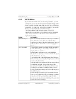
Page 105: ...ted Overwrite The same file name is always used and any existing file will be overwritten with the current file Increment A number from 000 to 255 is added to the file name and automatically incremented by 1 When it reaches 255 it starts again from 000 Date time suffix The date and time are automatically added to the file name When setting this parameter please ensure that the date and time of the...

Page 106: ...ding Scheduler Figure 12 15 Recording Submenus 12 4 Storage Medium Menu The Storage Medium menu allows the user to select an iSCSI system storage medium to configure the recording parameters Otherwise set to Off Figure 12 16 Storage Medium Menu FTP Server Password Allows the user to enter the password that gives access to the FTP server Path on FTP Server Allows the user to enter the exact path to...

Page 107: ...stablished The iSCSI LUN map field contains the corresponding logical drives iSCSI LUN Map The LUN map displays the logical drives configured for the iSCSI storage device The current user is displayed for each drive Double click a free drive LUN The associated information is called up and automatically displayed in the fields below the map If the logical drive is password protected you must first ...

Page 108: ...rive Target LUN Used to enter the LUN of the required drive Target Password If the drive is password protected enter the password You may not enter a new password This is only possible by configuring the iSCSI storage device Initiator Name Automatically displayed after a connection has been established Initiator Extension Used to enter the initiator extension For clarity enter a name or the existi...

Page 109: ...ology you must enter the data manually so that the AutoDome Easy IP can access the drive In this case you should ensure that the entries correspond exactly with the configuration of the iSCSI device After entering all the settings in the relevant fields click Set The AutoDome Easy IP attempts to create a connection to the required drive using this data As soon as a connection is established the se...

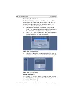
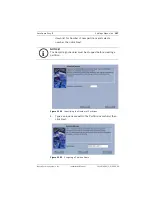
Page 110: ...IP Livepage then click the Settings link followed by the Recording drop down menu then click iSCSI The iSCSI screen is displayed 2 Double click a drive that is already being used in the iSCSI LUN Map a warning message is displayed Figure 12 18 Warning message 3 Confirm the decoupling of the current user The drive is released and can be connected to the AutoDome Easy IP Figure 12 19 iSCSI dialog bo...

Page 111: ...fore setting a partition you must choose a Storage Medium by going to the Settings page and clicking on the Recording Settings button Parameters such as size and type of video recording can be specified for each partition Modifying these parameters leads to reorganization which results in the loss of stored data The unit requires a dedicated partition for the recordings of each connected camera A ...

Page 112: ...tup on the hard drive After startup you can select the total number of partitions to be setup The setup process is then started as often as is necessary to configure all partitions To create a partition do the following 1 Open the AutoDome Easy IP Livepage then click the Settings link 2 Click the Recording drop down list then click Partitioning The AutoDome Easy IP displays the Partitioning screen...

Page 113: ...down list for Number of new partitions and select a number then click Next Figure 12 22 Identifying the Number of Partitions 4 Type a unique name within the Partition name field then click Next Figure 12 23 Assigning a Partition Name i NOTICE The Recording Scheduler must be stopped before creating a partition ...

Page 114: ...er of alarm tracks then click Calculate The AutoDome Easy IP displays the Calculation of alarm track size screen Figure 12 24 Alarm Track Recording Properties 6 Select a value for the Pre alarm profile the Pre alarm time the Post alarm profile and the Post alarm time Then click Set to save your settings Figure 12 25 Calculation of Alarm Track Size ...

Page 115: ...uously If the maximum hard drive space has been reached the oldest recordings are overwritten automatically Linear mode the recording proceeds until the entire hard drive space is full The recording is then stopped until old recordings have been deleted Figure 12 26 Type of Recording 8 Select one of the following methods to specify the partition size Type the Total partition size see Figure 12 27 ...

Page 116: ...9609 1 0 2008 08 Installation Manual Bosch Security Systems Inc Figure 12 27 Partitioning Size Click the Calculate button see Figure 12 27 The AutoDome Easy IP displays Calculation of parti tion size screen Figure 12 28 Calculating Partition Size ...

Page 117: ...ere To view the Partition status do the following 1 Open the AutoDome Easy IP Livepage then click the Settings link 2 Click the Recording drop down list then click Partitioning The Partitioning window is displayed 3 Click the camera that you would like to view Figure 12 29 Viewing a Partition 4 Click the Partition status button The AutoDome Easy IP displays the Partition status screen Figure 12 30...

Page 118: ... of the current partition configuration which can be modified at any time All modifications result in the reorganization of the partition and all sequences stored are lost It is recommended to back up all important sequences before modifying the partition The unit uses a special recording mode during alarm recording for optimal usage of storage capacity as soon as a time gap for alarm recording be...

Page 119: ...n Make any desired changes then click the Format button to save the modifications 5 Click the Type of recording drop down list and select the number of alarm tracks to be used in the partition One alarm event can be recorded in each alarm track and the number of alarms entered can be recorded and archived A partition can contain a maximum of 128 alarm recordings 6 Click the Set button when finishe...

Page 120: ...artitions cannot be deleted Click the Delete all partitions button The display retains the lines containing the numbers the partition names are deleted and 0 is specified as the size in each case CAUTION Check the recordings before deleting and back up important sequences on the computer s hard drive CAUTION Consequently you should check the recordings before deleting any partitions and backup imp...

Page 121: ...the Recording Profile do the following 1 Open the AutoDome Easy IP Livepage then click the Settings link 2 Click the Recording drop down list then click Recording Profiles The AutoDome Easy IP displays the Recording Profiles screen 3 Click the name of the camera input to edit the settings To select multiple camera inputs hold down the shift or Ctrl key 4 Click the Standard Profile drop down list a...

Page 122: ...k the Alarm input and the Video loss checkbox to activate these features 9 Click the Default button to return all settings to the default if appropriate 10 Click the Copy settings button to copy the currently visible settings to other profiles The AutoDome Easy IP opens a new Copy settings window then select the profiles to copy the settings 11 Click the Set button to save the settings for each pr...

Page 123: ...drop down list then click Recording Scheduler The Recording Scheduler screen is displayed 3 Click the profile you want to link in the Time periods field 4 Click in a field in the table hold down the mouse button and drag the cursor over all the periods to assign the selected profile 5 Use the right mouse button to deselect any of the intervals 6 Click the Select all button to link all time interva...

Page 124: ...y days that have already been selected will be shown in the table 2 Click the Add button the AutoDome Easy IP displays the Add holiday screen Figure 12 34 Adding a Holiday Menu 3 Select the desired date from the calendar To select several consecutive calendar days click and drag the mouse over the days The Recording Scheduler displays these days as a single entry in the table 4 Click OK to accept ...

Page 125: ...tivate the recording scheduler and start the recording Once recording is underway the Recording profile and Recording scheduler pages are deactivated and the configuration cannot be modified To stop the recording activity at any time to modify the settings do the following 1 Click the Start button to activate the recording scheduler 2 Click the Stop button to deactivate the recording scheduler Thi...

Page 126: ...arm Sources Menu 12 9 2 Alarm Connections The Alarm Connections screen allows users to specify up to ten 10 IP addresses which the device attempts to establish a connection with in the event of an alarm The device contacts the first specified IP address and then each subsequent address until the device establishes a connection Figure 12 36 Alarm Connections Menu To connect an alarm do the followin...

Page 127: ... an IP address 6 Click inside the Destination password input box and type the appropriate password for the IP address if required 7 Click the Video transmission drop down list and make a selection UDP or TCP HTTP Port 8 Click the Remote port drop down list and make a selection Depending on the network configuration select a browser port here The ports for HTTPS connections will be available only i...

Page 128: ...larm is triggered To configure for Alarm e mails do the following 1 Open the AutoDome Easy IP Livepage then click the Settings link 2 Click the Alarm drop down list then click Alarm E Mail The AutoDome Easy IP displays the Alarm E Mail screen Figure 12 37 Sending an Alarm E mail 3 Select On from the Send alarm e mail drop down list to automatically send an e mail in the event of an alarm 4 Type th...

Page 129: ... settings 10 To test the e mail function click the Send Now button 12 10 Service Main Menu The Service main menu contains the following submenus Network Multicasting Encryption Version Information Livepage Configuration Licenses and Maintenance 12 10 1 Network Menu The AutoDome Easy IP incorporates a network video server in the IP module To configure the camera using the AutoDome Easy IP Web serve...

Page 130: ...o save the settings 9 Launch another instance of Microsoft Internet Explorer 10 Type the original IP address followed by reset to restart the AutoDome Easy IP For example type http 192 168 0 1 reset in the address bar and click Go 11 Once you restart the AutoDome Easy IP use the new IP Address to access the LivePage 12 Disconnect the AutoDome Easy IP Ethernet cable from the dedicated network switc...

Page 131: ... This Multicast IP address can be the same for multiple encoder devices If you do use the same address however you must define a different port number in each device so that the encoder does not send multiple data streams over the same port and the Multicast IP address The address range is from 225 0 0 0 to 239 255 255 255 The multicast address can be the same for multiple AutoDome Easy IP units M...

Page 132: ... enter the activation key to release the function on the Licenses page see 12 10 6 Licenses To work with encrypted data transmission allow only secured Web browser connection with SSL encryption by deactivating all open ports and protocols see Network Connections are then only possible via the HTTPS port The user has the option of selecting individual data channels for the encryption As soon as a ...

Page 133: ...ncryption 4 Click the Keys button to edit the Encryption screen Figure 12 41 Encryption Edit screen 5 Click an entry in the list 6 Hold the Ctrl key down to select multiple entries 7 Click the Clear keys button to delete the selected key 8 Click the Generate keys button to generate a new key for a selected channel 9 Click Edit to enter a key for a selected entry Automatic Key Interchange Check the...

Page 134: ...ions to display specific device information and operating elements in addition to the video image Note You can use either GIF or JPEG images as the banner image The file paths must correspond to the access mode for example C Images Logo gif for access to local files or http www bosch com images logo gif for access via the Internet or Intranet Company Logo Type the fully qualified path to a backgro...

Page 135: ...tem messages and the date and time in a field next to the video image Save Event Log Check this option to save event messages in a text file on your local computer You can then view edit and print this file with any text editor or the standard Office software Save System Log Check this option to save system messages in a text file on your local computer You can then view edit and print this file w...

Page 136: ...he activation key in this window The activation key cannot be deactivated again and is not transferable to other units Figure 12 44 License Menu 12 10 7 Maintenance A firmware upload allows the user to update the firmware and configuration parameters or to upload configuration parameters to a computer The automatic installation allows you to remotely service and update the device You can obtain th...

Page 137: ...P Firmware Upload window that lists applicable updates The system loads the updates automatically 4 Click Upload Firmware 5 The installation program unpacks the firmware and updates the Flash EPROM memory The unit restarts automatically once the upload has successfully completed 6 If the Connect LED lights up red the upload has failed and must be repeated To perform the upload you must now switch ...

Page 138: ... Certificate Upload To be able to work with an SSL encrypted data connection both ends of a connection must hold the relevant certificates You can upload the SSL certificate comprising one or multiple files onto the AutoDome Easy IP To upload multiple files onto the AutoDome Easy IP select them consecutively 1 Type the full path of the file to upload or click Browse to select the required file 2 C...

Page 139: ...AutoDome Easy IP Settings Menus en 133 Bosch Security Systems Inc Installation Manual F01U079609 1 0 2008 08 ...

Page 140: ... 1 Activate deactivate Aux Off 65 Alarm acknowledge Acknowledges the alarm and reverts to its pre alarm PTZ condition Aux On 66 Displays firmware version Displays firmware version number Set Shot 1 60 Pre position programming Set programs a preset view Show Shot 1 60 Pre position recall Shot recall programmed preset Set Shot 110 Factory P T home position Set recalibrate home position Show Shot 201...

Page 141: ...AutoDome Easy IP Keyboard Commands by Number en 135 Bosch Security Systems Inc Installation Manual F01U079609 1 0 2008 08 ...

Page 142: ...t Inspect all connecting cables for deterioration or other damage Wipe housing with a clean damp cloth Clean P C LEXAN dome windows with an approved P C LEXAN cleaner Novus LEXAN cleaner plastic polish Verify that all the mounting hardware is secure Part number location Description F01U079020 Covert liner Wire harness assembly F01U079021 Bubble assembly F01U082463 User manual F01U079029 Accessory ...

Page 143: ...AutoDome Easy IP Preventive Maintenance en 137 Bosch Security Systems Inc Installation Manual F01U079609 1 0 2008 07 ...

Page 144: ...without removing the bubble and covert liner If no LEDs are lit there may be a problem with power to the dome Do you get a valid reply if you ping the dome s IP address from a DOS command prompt see below If not use the Configuration Manager tool to scan the network for the IP addresses of Autodome Easy IP domes found on the network and to confirm that no two 2 domes have the same IP address If yo...

Page 145: ...for NTSC model cameras and 50 Hz for PAL model cameras If this is not the case then change the synchronization mode to INTernal in the camera s OSD menu Forgot password or want to reset it Call Technical Support for assistance Protocol switch mismatch Set your settings as per 7 Setting Protocol and Video Format page 33 Cannot set IP address Check with your IT network administrator that the IP addr...

Page 146: ... does not boot up and is stuck in the initial blue software version screen Did you remember to remove the clear protective plastic sheet on top of the bubble and the blue protective foam packaging between the bubble and the PTZ assembly for shipment Does the camera perform its PTZ homing routing when powered up Video is too dark Did you restore all the camera settings Is the gain control set to Au...

Page 147: ...age 142 Note You may need to remove the cover to view the LEDs Did you check that you are not mixing up straight CAT 5E or CAT 6 and crossover CAT 5E or CAT 6 cables You should use a crossover cable when the PC is directly connected to the dome and a straight cable when it is connected through a switch See Figure 8 1 on page 39 Can you access the dome using the Configuration Manager tool which sca...

Page 148: ... LED status indicators D0403 Red Network link Link OK Link failure Link active Note LEDs D0401 D0402 and D0403 will only turn off if there is a good network connection between the IP board and the PC Note You may need to remove the bubble and the covert liner to see the LEDs completely LED Color Function ON OFF Flashing ...

Page 149: ...hase 19 33 Bosch MPEG ActiveX 37 C cable assembly 20 cables alarm 18 distance guide 18 power 17 distance guide 17 UTP CAT 5 17 camera operations 46 Camera Setup menu 53 54 line lock delay line lock 74 synchronization mode crystal 74 line lock 74 command number 49 commands reset 43 124 Aux Off 49 Aux On 49 keyboard 49 133 preset shot 51 Set Shot 49 51 Show Shot 49 Configuration Manager 40 configuri...

Page 150: ...15 keyboard commands 49 50 133 Aux Off command 49 Aux On 49 keypad 50 L line lock 74 Livepage 42 45 123 locking torx wrench 13 M menus 53 M JPEG 46 mounting bracket 13 MPEG 4 37 MPEG 4 Stream 1 46 MPEG 4 Stream 2 46 multicast 35 N network settings page 124 networking Ethernet cable 39 gateway address 38 IGMP V2 35 IP 35 IP address 38 port 38 subnet mask 38 TCP IP 35 UDP 35 P partition 105 Partitio...

Page 151: ...tings protocol 33 Setup menu Alarms 53 Camera 53 54 Show Shot command 49 snapshots 36 software DirectX 37 standard profile 115 subnet mask 38 switches 0 33 9 33 system log 48 T TCP IP 35 torx wrench 13 30 U UDP 35 UTP CAT 5 17 V video formats 33 View Control tab 46 W wires alarm 17 18 distance guide 18 control 17 power 17 distance guide 17 video 17 wiring 17 Z zoom 46 ...

Page 152: ...146 en Index AutoDome Easy IP F01U079609 1 0 2008 08 Installation Manual Bosch Security Systems Inc ...

Page 153: ...ity Systems Inc 850 Greenfield Road Lancaster PA 17601 USA Telephone 800 366 2283 Fax 800 366 1329 www boschsecurity com Bosch Security Systems Inc 2008 F01U079609 1 0 2008 08 Data subject to change without notice ...

Reviews: