background image

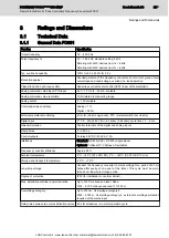
3.1.3 

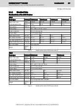
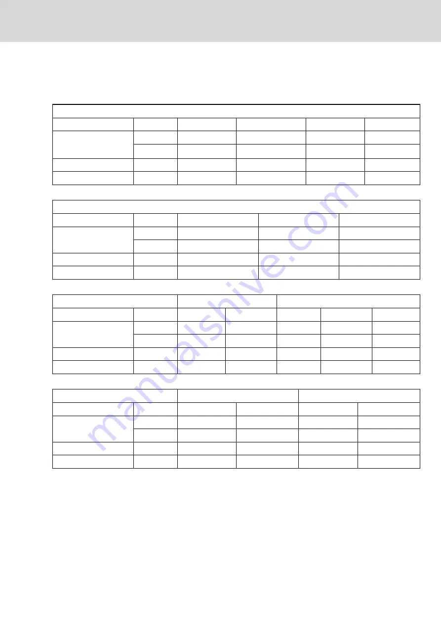
Electrical Data for UL Approval

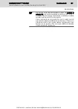
The data specified in this paragraph must be considered to comply with the

UL approval.

Size A - 230 V mains
Device type:

FCS01.1E

-W0003-A-02

-W0005-A-02

-W0006-A-02

-W0008-A-02

Rated motor power
(4-pole standard motor)

220V

0.25 kW

0.37 kW

0.55 kW

0.75 kW

240V

1

/

3

 hp

½ hp

¾ hp

1 hp

FLA 1/3 AC

[A]

4 / 3

5 / 4

7 / 5

9 / 6

Recom. mains fuse

J Class Fuse LPJ 10A

LPJ 10A

LPJ 16A / 10A

LPJ 16A / 10A

Fig.3-6:

Electrical Data for UL Approval (Size A - 230V Mains)

Size B - 230V mains
Device type:

FCS01.1E

W0011-A-02

W0015-A-02

W0019-A-02

Rated motor power
(4-pole standard motor)

220V

1.1 kW

1.5 kW

2.2 kW

240V

1½ hp

2 hp

3 hp

FLA 1/3 AC

[A]

11 / 8

14 / 10

19 / 13

Recom. mains fuse

J Class Fuse LPJ 16A

LPJ 16A

LPJ 20A

Fig.3-7:

Electrical Data for UL Approval (Size B - 230V Mains)

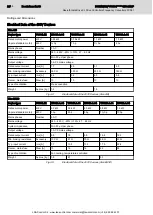
Size A/B - 400V mains

A

B

Device type:

FCS01.1E

W0003-A-04

W0005-A-04

W0006-A-04 W0008-A-04

W0011-A-04

Rated motor power
(4-pole standard motor)

380V

0.55 kW

0.75 kW

1.1 kW

1.5 kW

2.2 kW

460…480V

¾ hp

1 hp

1½ hp

2 hp

3 hp

FLA 1/3 AC

[A]

4

4

5

6

8

Recom. mains fuse

J Class Fuse LPJ 10A

LPJ 10A

LPJ 10A

LPJ 10A

LPJ 10A

Fig.3-8:

Electrical Data for UL Approval (Size A/B - 400V Mains)

Size C/D - 400V mains

C

D

Device type:

FCS01.1E

W0015-A-04

W0019-A-04

W0025-A-04

W0032-A-04

Rated motor power
(4-pole standard motor)

380V

3.0 kW

4.0 kW

5.5 kW

7.5 kW

460…480V

4 hp

5 hp

7½ hp

10 hp

FLA 1/3 AC

[A]

11

13

17

21

Recom. mains fuse

J Class Fuse LPJ 16A

LPJ 16A

LPJ 20A

LPJ 25A

Fig.3-9:

Electrical Data for UL Approval (Size C/D - 400V Mains)

DOK-INDRV*-FCS01******-IT01-EN-P 
Rexroth IndraDrive Fc Drive Controllers Frequency Converters FCS01 

Bosch Rexroth AG

27/69

Ratings and Dimensions

LSA Control S.L. www.lsa-control.com [email protected] (+34) 960 62 43 01

Summary of Contents for Rexroth IndraDrive FC Series

Page 1: ...Controls Pneumatics Service Linear Motion and Assembly Technologies Hydraulics Rexroth IndraDrive Fc Drive Controllers Frequency Converters FCS01 R911339118 Edition 01 LSA Control S L www lsa control com comercial lsa control com 34 960 62 43 01 ...
Page 2: ... its consent Liability The specified data is intended for product description purposes only and shall not be deemed to be a guaranteed characteristic unless expressly stipulated in the contract All rights are reserved with respect to the content of this docu mentation and the availability of the product Published by Bosch Rexroth AG Bgm Dr Nebel Str 2 97816 Lohr a Main Germany Telephone 49 0 93 52...

Page 3: ...Tenez compte des délais de décharge de condensateurs Gefahrbringende Bewegungen Lebensgefahr Halten Sie sich nicht im Bewegungsbereich von Maschinen und Maschinenteilen auf Verhindern Sie den unbeabsichtigten Zutritt für Personen Bringen Sie vor dem Zugriff oder Zutritt in den Gefahrenbereich die Antriebe sicher zum Stillstand Dangerous movements Danger to life Keep free and clear of the ranges of...

Page 4: ...ntes de acionamento Explicações mais detalhadas relativamente às instruções de segurança constam no capítulo 1 desta documentação Pericolo di morte in caso di inosservanza delle seguenti indicazioni di sicurezza Mettere in funzione i prodotti solo dopo aver letto compreso e osservato per intero la documentazione e le indicazioni di sicurezza fornite con il prodotto Se non dovesse essere presente l...

Page 5: ... baterias Não deite as baterias no fogo Utilizzo inappropriato delle batterie Pericolo di lesioni Non tentare di riattivare o ricaricare batterie scariche pericolo di esplosione e corrosione Non scomporre o danneggiare le batterie Non gettare le batterie nel fuoco Svenska Dansk Nederlands Livsfara om följande säkerhetsanvisningar inte följs Använd inte produkterna innan du har läst och förstått de...

Page 6: ...dröra metallytor t ex kylelement Var medveten om att det tar tid för drivkomponenterna att svalna minst 15 minuter Varme overflader 60 C Risiko for forbrændinger Undgå at berøre metaloverflader f eks køleelementer Overhold drive components nedkølingstid min 15 min Hete oppervlakken 60 C Verbrandingsgevaar Voorkom contact met metalen oppervlakken bijv Koellichamen Afkoeltijd van de aandrijvingscomp...

Page 7: ...ýt v provozu pouze s pevně nainstalovaným ochranným vodičem Než začnete zasahovat do komponent pohonu odpojte je od elektrického napájení Dodržujte vybíjecí časy kondenzátorů Vaarallisia liikkeitä Hengenvaara Älä oleskele koneiden tai koneenosien liikealueella Pidä huolta siitä ettei muita henkilöitä pääse alueelle vahingossa Pysäytä käyttölaitteet varmasti ennen vaara alueelle koskemista tai mene...

Page 8: ...ým pokynom zistite z kapitoly 1 tejto dokumentácie Pericol de moarte în cazul nerespectării următoarelor instrucţiuni de siguranţă Punerea în funcţiune a produselor trebuie efectuată după citirea înţelegerea şi respectarea documentelor şi instrucţiunilor de siguranţă care sunt livrate împreună cu produsele În cazul în care documentele nu sunt în limba dumneavoastră maternă vă rugăm să contactaţi p...

Page 9: ...ţi să reactivaţi sau să încărcaţi bateriile goale pericol de explozie şi pericol de arsuri Nu dezasamblaţi şi nu deterioraţi bateriile Nu aruncaţi bateriile în foc Magyar Български Latviski Az alábbi biztonsági útmutatások figyelmen kívül hagyása életveszélyes helyzethez vezethet Üzembe helyezés előtt olvassa el értelmezze és vegye figyelembe a csomagban található dokumentumban foglaltakat és a bi...

Page 10: ... hűtőtestekhez Vegye figyelembe a hajtás alkatrészeinek kihűlési idejét min 15 perc Горещи повърхности 60 C Опасност от изгаряне Не докосвайте метални повърхности например радиатори Съблюдавайте времето на охлаждане на задвижващите компоненти мин 15 минути Karstas virsmas 60 C Apdedzināšanās risks Neskarieties pie metāliskām virsmām piemēram dzesētāja Ļaujiet piedziņas komponentiem atdzist min 15 ...

Page 11: ...χρόνους αποφόρτισης των πυκνωτών Pavojingi judesiai Pavojus gyvybei Nebūkite mašinų ar jų dalių judėjimo zonoje Neleiskite netyčia patekti asmenims Prieš patekdami į pavojaus zoną saugiai išjunkite pavaras Ohtlikud liikumised Eluohtlik Ärge viibige masina ja masinaosade liikumispiirkonnas Tõkestage inimeste ettekavatsematu sisenemine masina ja masinaosade liikumispiirkonda Tagage ajamite turvaline...

Page 12: ... reaktiveerida või täis laadida plahvatus ja söövitusoht Ärge demonteerige ega kahjustage patareisid Ärge visake patareisid tulle Ακατάλληλος χειρισμός μπαταριών Κίνδυνος τραυματισμού Μην επιδιώκετε να ενεργοποιήσετε ξανά ή να φορτίσετε κενές μπαταρίες κίνδυνος έκρηξης και διάβρωσης Μην διαλύετε ή καταστρέφετε τις μπαταρίες Μην απορρίπτετε τις μπαταρίες στη φωτιά 中文 如果不按照下述指定的安全说明使用 将会导致人身伤害 在没有阅读...

Page 13: ...ices 26 3 1 3 Electrical Data for UL Approval 27 3 2 Dimensions of the FCS01 Frequency Converter 28 3 3 Installation 28 4 Reference Documentations 31 4 1 Documentations Overview 31 5 Instructions for Use 33 5 1 Wiring Directives 33 5 1 1 General Information 33 5 1 2 Line Routing and Shielding at Function Modules 34 5 1 3 EMC Limit Value Classes to be Achieved 34 5 1 4 Wiring Recommendations for Po...

Page 14: ...trol Cabinet 53 6 2 6 Design and Installation in Area C Strongly Interference Susceptible Area of Control Cabinet 53 6 3 Ground Connections 54 6 4 Installing Signal Lines and Signal Cables 55 6 5 General Measures of Radio Interference Suppression for Relays Contactors Switches Chokes and Inductive Loads 56 7 Accessories 57 7 1 Components for IndraDrive Fc 57 7 2 Type Code FCC01 Function Module 58 ...

Page 15: ...th these qualifications it is necessary among other things to be trained instructed or authorized to switch electric circuits and components safely on and off to ground them and to mark them to be trained or instructed to maintain and use adequate safety equipment to attend a course of instruction in first aid The technical data connection and installation conditions of the compo nents are specifi...

Page 16: ...the power supply unit Secure the electric component from reconnec tion With electric components observe the following aspects Always wait 30 minutes after switching off power to allow live capacitors to discharge before accessing an electric component Measure the elec trical voltage of live parts before beginning to work to make sure that the equipment is safe to touch Install the covers and guard...

Page 17: ...1 3 Protection Against Dangerous Movements Dangerous movements can be caused by faulty control of connected motors Some common examples are Improper or wrong wiring or cable connection Operator errors Wrong input of parameters before commissioning Malfunction of sensors and encoders Defective components Software or firmware errors These errors can occur immediately after equipment is switched on o...

Page 18: ... power connection by means of OFF switches OFF buttons or use a safe starting lockout Make sure that the drives are brought to safe standstill before accessing or entering the danger zone Additionally secure vertical axes against falling or dropping after switch ing off the motor power by for example mechanically securing the vertical axes adding an external braking arrester clamping mechanism or ...

Page 19: ...ric drive and control system Risk of burns Do not touch hot surfaces of for example braking resistors heat sinks supply units and drive controllers motors windings and laminated cores According to the operating conditions temperatures of the surfaces can be higher than 60 C 140 F during or after operation Before touching motors after having switched them off let them cool down for a sufficient per...

Page 20: ...e battery batteries do not damage the electrical parts installed in the devices Only use the battery types specified for the product Environmental protection and disposal The batteries contained in the product are considered dangerous goods during land air and sea transport risk of explosion in the sense of the legal regula tions Dispose of used batteries separately from other waste Ob serve the n...

Page 21: ...ded for use in a public low volt age network supplying residential areas with power If these com ponents are used in such a public network high frequency inter ference is to be expected This can require additional measures of radio interference suppression DOK INDRV FCS01 IT01 EN P Rexroth IndraDrive Fc Drive Controllers Frequency Converters FCS01 Bosch Rexroth AG 19 69 Important Notes LSA Control...

Page 22: ...Bosch Rexroth AG DOK INDRV FCS01 IT01 EN P Rexroth IndraDrive Fc Drive Controllers Frequency Converters FCS01 20 69 LSA Control S L www lsa control com comercial lsa control com 34 960 62 43 01 ...
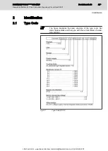
Page 23: ...resentative will help you with the current status of availa ble versions Fig 2 1 Type Code FCS01 DOK INDRV FCS01 IT01 EN P Rexroth IndraDrive Fc Drive Controllers Frequency Converters FCS01 Bosch Rexroth AG 21 69 Identification LSA Control S L www lsa control com comercial lsa control com 34 960 62 43 01 ...
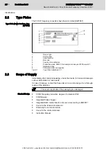
Page 24: ... parts In case of damage contact the forwarder at once and arrange for a thorough review of the situation This is also applicable if the packaging is undamaged Standard Design FCS01 frequency converter degree of protection IP20 FCB firmware Integrated brake chopper Integrated EMC mains filter for limit curve A according to EN55011 Cover for the function module slot Shield clip for control terminal...

Page 25: ...igital and analog inputs Ramp times 0 320 0 s Control outputs 2x relay 28V DC 230V AC 2A Interfaces Standard RS 485 USS RS 232 single slave Optional Profibus DP CANopen DeviceNet Frequency converter efficiency Approx 95 Ambient temperature 0 C 40 C S1 100 ED 0 C 50 C S3 75 ED 10 min Storage and transport temperature 25 C 70 C Long time storage Connect the frequency converter to mains voltage for a...

Page 26: ...r stranded wire with ferrules AWG 26 16 Relay 0 14 1 5 mm2 stranded wire with ferrules 0 14 2 5 mm2 solid wire AWG 26 14 RS485 RS232 1x RJ12 6 pin CANbus Fig 3 1 General Data FCS01 Bosch Rexroth AG DOK INDRV FCS01 IT01 EN P Rexroth IndraDrive Fc Drive Controllers Frequency Converters FCS01 24 69 Ratings and Dimensions LSA Control S L www lsa control com comercial lsa control com 34 960 62 43 01 ...
Page 27: ...l Data of the 230V Devices Size A Size B Device type FCS01 1E W0011 A 02 W0015 A 02 W0019 A 02 Rated motor power 4 pole standard motor 230 V 1 1 kW 1 5 kW 2 2 kW 240 V 1 hp 2 hp 3 hp Mains phases Number 1 3 AC Mains voltage 200 240 V 10 47 63 Hz System impedance Min 100 μH per phase Output voltage 3 AC 0 mains voltage Rated output current rms A 5 5 7 0 9 0 9 5 Min braking resistance Accessory 75 Ω...

Page 28: ...S01 1E W0011 A 04 W0015 A 04 W0019 A 04 W0025 A 04 W0032 A 04 Rated motor power 4 pole standard motor 400 V 2 2 kW 3 0 kW 4 0 kW 5 5 kW 7 5 kW 480 V 3 hp 4 hp 5 hp 7 hp 10 hp Mains phases Number 3 AC Mains voltage 380 480 V 20 10 47 63 Hz System impedance Min 50 μH per phase Output voltage 3 AC 0 mains voltage Rated output current rms A 5 5 7 5 9 5 12 5 16 0 Min braking resistance Accessory 130 Ω ...

Page 29: ...oval Size B 230V Mains Size A B 400V mains A B Device type FCS01 1E W0003 A 04 W0005 A 04 W0006 A 04 W0008 A 04 W0011 A 04 Rated motor power 4 pole standard motor 380V 0 55 kW 0 75 kW 1 1 kW 1 5 kW 2 2 kW 460 480V hp 1 hp 1 hp 2 hp 3 hp FLA 1 3 AC A 4 4 5 6 8 Recom mains fuse J Class Fuse LPJ 10A LPJ 10A LPJ 10A LPJ 10A LPJ 10A Fig 3 8 Electrical Data for UL Approval Size A B 400V Mains Size C D 4...

Page 30: ... 04 FCS01 1E W0032 A 04 D 286 98 178 320 5 5 Fig 3 11 Dimensions of the FCS01 Frequency Converters 3 3 Installation The FCS01 frequency converters are supplied in different sizes depending on the power Whe mounting the frequency converter observe the allowed mounting position To be protected from overheating the devices must be sufficiently ventilated For this purpose guide values apply for minimu...

Page 31: ... recommend that you mount an obstacle e g a cable duct between the frequency converters which will interrupt the direct air flow ris ing warm air Efficiency For installation in a control cabinet ensure sufficient ventilation During operation dissipation heat is approx 5 depending on the device size and equipment of the nominal power of the frequency converter DOK INDRV FCS01 IT01 EN P Rexroth Indr...

Page 32: ...Bosch Rexroth AG DOK INDRV FCS01 IT01 EN P Rexroth IndraDrive Fc Drive Controllers Frequency Converters FCS01 30 69 LSA Control S L www lsa control com comercial lsa control com 34 960 62 43 01 ...
Page 33: ...anual DOK DRIVE 3RDPART MOT AWxx EN P Safety Instructions for Electric Drives Safety Guidelines DOK GENERAL DRIVE SVSx MS P 1 In the document typecodes xx is a wild card for the current edition of the documentation example PR01 is the first edition of a Project Planning Manual Fig 4 1 Documentations Overview DOK INDRV FCS01 IT01 EN P Rexroth IndraDrive Fc Drive Controllers Frequency Converters FCS...

Page 34: ...Bosch Rexroth AG DOK INDRV FCS01 IT01 EN P Rexroth IndraDrive Fc Drive Controllers Frequency Converters FCS01 32 69 LSA Control S L www lsa control com comercial lsa control com 34 960 62 43 01 ...

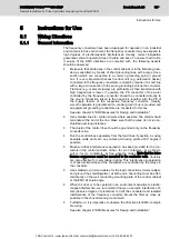
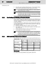
Page 35: ...nate at the end of the line Make sure that the wires do not run un shielded over long distances The shield of the control lines should be grounded only on the frequency converter side Run the control lines separately from the load lines if possible by using separate cable ducts etc Lay cables at crossing points at 90 angles if possible Make sure that interference suppression has been provided for ...

Page 36: ...s between bus nodes as short as possible The shielding of the bus cable must be placed on both sides over a large surface area Avoid connecting field devices to the bus via branch circuits Avoid extending bus cables via connectors In the case of different potentials to ground a compensating cur rent may flow through the shield connected on both sides which is a potential risk to the electronic com...

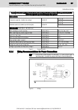
Page 37: ... 1 kV Burst on mains lines and motor lines EN 61000 4 4 2 kV Surge phase phase ground EN 61000 4 5 1 kV 2 kV Conducted disturbance by high frequency fields EN 61000 4 6 10 V 0 15 80 MHz Voltage fluctuations and voltage dips EN 61000 2 1 10 15 90 Voltage asymmetries and frequency changes EN 61000 2 4 3 2 Fig 5 1 Noise Immunity 5 1 4 Wiring Recommendations for Power Connections Connect the cable shi...

Page 38: ...ted on the bottom of the frequency converter The control terminals are situated on the front of the frequency converter To reach them push the terminal cover downwards and pull it off Now the ter minals are accessible from the front Re fit all covers before switching on the supply voltage The following must be observed Make sure that the voltage source supplies the correct voltage and has been siz...

Page 39: ...6 14 AWG Relay 1 5 mm 2 26 16 AWG Control lines Run and shield separately from mains motor lines Control voltages 5V 20 max 250 mA short circuit proof 10V max 5 mA reference voltage for an ext potentiom eter 15V 20 max 150 mA for supplying the dig inputs Analog output 0 10V max 20 mA for an ext display unit DOK INDRV FCS01 IT01 EN P Rexroth IndraDrive Fc Drive Controllers Frequency Converters FCS0...

Page 40: ...V power supply 5V 20 250 mA Fig 5 4 X2 Terminal Block 5 2 3 X3 Mains Connection PE L1 L2 N L3 General Information The frequency converter does not require any specific kind of fusing at the power input side We recommend that you use the usual mains fuses and a main switch or contactor See also chapter 3 Technical Data 230V devices of up to 2 2 kW may either be operated with 1 phase 230V L N L1 L2 ...

Page 41: ...on Via jumpers at the top and bottom of the device the FCS01 frequency con verters can be set for operation at IT mains and for reduction of leakage cur rents At the Top of the Device Mains Input Fig 5 6 Mains Input Jumper in Position 2 Setting Position Effect 0 Operation at the IT mains 1 No effect 2 Standard position condition as supplied Fig 5 7 Jumper Position at the Top DOK INDRV FCS01 IT01 E...

Page 42: ...device Position of jumper at bottom of device Explanation IT mains 0 0 Residual current operated circuit breaker 0 1 or 2 2 Fig 5 10 Settings Be aware that the specified degree of radio interference suppres sion may change with the different settings For details please see chapter 6 EMC Measures for Design and Installation Bosch Rexroth AG DOK INDRV FCS01 IT01 EN P Rexroth IndraDrive Fc Drive Cont...

Page 43: ...n For operation with several motors the total motor cable length is the sum of all individual cable lengths Fig 5 12 Motor Cable 5 2 5 X5 Connection of Braking Resistor B B The terminals B B are provided for connection of a suitable braking resis tor For the connection select a twisted and shielded line which is as short as possible maximum allowed length 2 x 5 m DOK INDRV FCS01 IT01 EN P Rexroth ...

Page 44: ...ption and utilization of braking resis tors Note the following aspects Keep the connecting line between B and DC as short as possible Make sure that the coupling is not provided before readiness for opera tion is signaled Otherwise there is the risk that the DC bus capacitors of all frequency converters are charged by only one frequency convert er Make sure that the coupling is disconnected if one...

Page 45: ...tion at the terminals 3 4 relay 2 When an error message is pending or when the frequency converter is de energized the contact is open The terminals 1 2 relay 1 can control a mechanical motor brake in the facto ry setting Only in this way is the brake released and applied again at the right moment To optimize the temporal sequence set the respective delay 0 2 0 3 s in parameter P107 DOK INDRV FCS0...

Page 46: ...g input controls the output fre quency of the frequency converter 12 AGND 0V Reference potential of the analog signals 0 V analog 14 AIN1 Analog input 1 0 10V Ri 10kΩ 0 4 20mA Ri 250Ω can be switched with DIP switch reference potential AGND P400 16 AIN2 Analog input 2 P405 17 AOUT1 Analog output 0 10 V 20 mA reference potential AGND Can be used for external display or fur ther processing in a seco...

Page 47: ...Ω suit able for PTC thermistor evaluation with 5V supply P424 42 VO 15V 15V power supply 15V 20 150 mA 40 DGND Reference potential of the digital signals 0 V digital 41 VO 5V 5V power supply 5 V 20 250 mA Power supply for motor PTC Fig 5 18 X36 Terminal Block Fig 5 19 Electrical Control Connection DOK INDRV FCS01 IT01 EN P Rexroth IndraDrive Fc Drive Controllers Frequency Converters FCS01 Bosch Re...

Page 48: ...Bosch Rexroth AG DOK INDRV FCS01 IT01 EN P Rexroth IndraDrive Fc Drive Controllers Frequency Converters FCS01 46 69 LSA Control S L www lsa control com comercial lsa control com 34 960 62 43 01 ...

Page 49: ...ousing or mounting pan els Separate the incoming and outgoing cables of the radio interference sup pression filter Interference Suppression Ele ments Provide the following components in the control cabinet with interference sup pression combinations Contactors Relays Solenoid valves Electromechanical operating hours counters Connect these combinations directly at each coil Twisted Wires Twist unsh...

Page 50: ...ts in the control cabinet See section Control Cabinet Design According to Interference Areas Exemplary Arrangements page 50 We distinguish three areas 1 Interference free area of control cabinet area A This includes Supply feeder input terminals fuse main switch mains side of mains filter for drives and corresponding connecting lines Control voltage or auxiliary voltage connection with power suppl...

Page 51: ...e middle and on the bot tom via short equipment grounding conductors with a cross section of at least 6 mm2 or even better via grounding straps with the same cross section Make sure connection points have good contact DOK INDRV FCS01 IT01 EN P Rexroth IndraDrive Fc Drive Controllers Frequency Converters FCS01 Bosch Rexroth AG 49 69 EMC Measures for Design and Installation LSA Control S L www lsa c...

Page 52: ...eding Supply Unit or Converter DR1 Mains choke optional Bosch Rexroth AG DOK INDRV FCS01 IT01 EN P Rexroth IndraDrive Fc Drive Controllers Frequency Converters FCS01 50 69 EMC Measures for Design and Installation LSA Control S L www lsa control com comercial lsa control com 34 960 62 43 01 ...

Page 53: ...distance of at least 200 mm distance d1 and d3 in the figure Between supply feeder or lines between filter and exit point from the control cabinet in area A and the lines in area B and C If this is impossible there are two alternatives 1 Install lines in shielded form and connect the shield at several points at least at the beginning and at the end of the line to the mounting plate or the control ...

Page 54: ...quired for long cables of more than 2 m be tween the point of power supply connection of the control cabinet and the fil ter within the control cabinet Mains Filters for AC Drives Ideally mount the mains filter on the parting line between the areas A and B Make sure the ground connection between filter housing and housing of the drive controllers has good electrically conductive properties If sing...

Page 55: ...le Area of Control Cabinet Area C mainly concerns the motor power cables especially at the connection point at the drive controller Influence of the Motor Power Ca ble The longer the motor power cable the greater its leakage capacitance To comply with a certain EMC limit value the allowed leakage capacitance of the mains filter is limited For the calculation of the leakage capacitance see the docu...

Page 56: ... Routing of Cables for Converter 6 3 Ground Connections Housing and Mounting Plate By means of appropriate ground connections it is possible to avoid the emis sion of interference because interference is discharged to ground on the shortest possible way Ground connections of the metal housings of EMC critical components such as filters devices of the drive system connection points of the cable shi...

Page 57: ...onnected at least at both ends so that they do not have any antenna effect Avoid unnecessary line lengths Run cables as close as possible to grounded metal surfaces reference potential The ideal solution are closed grounded cable ducts or metal pipes which however is only obligatory for high requirements sensitive instrument leads Avoid suspended lines or lines routed along synthetic carriers beca...

Page 58: ... case of a c operation by arranging usual RC interference sup pression elements depending on the contactor type immediately at the inductance Only the interference suppression element arranged immediately at the in ductance does serve this purpose Otherwise the emitted noise level is too high which can affect the function of the electronic system and of the drive Bosch Rexroth AG DOK INDRV FCS01 I...

Page 59: ...01 braking resistors Additional component FAS02 To connect the motor cable shield to the housing of the frequency converter DriveTop Fc software For parameterization and commissioning Any other accessories on request DOK INDRV FCS01 IT01 EN P Rexroth IndraDrive Fc Drive Controllers Frequency Converters FCS01 Bosch Rexroth AG 57 69 Accessories LSA Control S L www lsa control com comercial lsa contr...

Page 60: ...ule Fig 7 2 Type Code FCS01 Bosch Rexroth AG DOK INDRV FCS01 IT01 EN P Rexroth IndraDrive Fc Drive Controllers Frequency Converters FCS01 58 69 Accessories LSA Control S L www lsa control com comercial lsa control com 34 960 62 43 01 ...

Page 61: ...king resistor can be used In this process the integrated power transistor brake chopper dis charges the DC bus voltage switching limit at approx DC420V or DC720V depending on type of FCS01 to the braking resistor Here the recovered en ergy is converted to heat DOK INDRV FCS01 IT01 EN P Rexroth IndraDrive Fc Drive Controllers Frequency Converters FCS01 Bosch Rexroth AG 59 69 Accessories LSA Control...

Page 62: ...ed with an op tional temperature switch FAS01 to prevent overloading The fixing material in the groove on the side is contained in the scope of supply of FLR01 1N The braking resistor and the temperature switch are connected via lines Bosch Rexroth AG DOK INDRV FCS01 IT01 EN P Rexroth IndraDrive Fc Drive Controllers Frequency Converters FCS01 60 69 Accessories LSA Control S L www lsa control com c...

Page 63: ...Connection Fig 7 5 Type Code FAS02 DOK INDRV FCS01 IT01 EN P Rexroth IndraDrive Fc Drive Controllers Frequency Converters FCS01 Bosch Rexroth AG 61 69 Accessories LSA Control S L www lsa control com comercial lsa control com 34 960 62 43 01 ...

Page 64: ...Bosch Rexroth AG DOK INDRV FCS01 IT01 EN P Rexroth IndraDrive Fc Drive Controllers Frequency Converters FCS01 62 69 LSA Control S L www lsa control com comercial lsa control com 34 960 62 43 01 ...

Page 65: ... and training can be found on our internet sites Service worldwide Outside Germany please contact your local service office first For hotline numbers refer to the sales office addresses on the internet Preparing information To be able to help you more quickly and efficiently please have the following information ready Detailed description of malfunction and circumstances resulting in the malfuncti...

Page 66: ...Bosch Rexroth AG DOK INDRV FCS01 IT01 EN P Rexroth IndraDrive Fc Drive Controllers Frequency Converters FCS01 64 69 LSA Control S L www lsa control com comercial lsa control com 34 960 62 43 01 ...

Page 67: ...exroth AG Electric Drives and Controls Buergermeister Dr Nebel Strasse 2 97816 Lohr am Main Germany Packaging The packaging materials consist of cardboard wood and polystyrene These materials can be recycled anywhere without any problem For ecological reasons please refrain from returning the empty packages to us Batteries and Accumulators Batteries and accumulators can be labeled with this symbol...

Page 68: ... plastic parts are labeled according to EN ISO 1043 They have to be recycled separately or disposed of according to the valid legal requirements Bosch Rexroth AG DOK INDRV FCS01 IT01 EN P Rexroth IndraDrive Fc Drive Controllers Frequency Converters FCS01 66 69 Environmental Protection and Disposal LSA Control S L www lsa control com comercial lsa control com 34 960 62 43 01 ...

Page 69: ...es 65 I IndraDrive Documentation 31 Installation 28 EMC measures 47 Ground connections 54 Signal lines 55 IT mains 39 M Mains filter Motor fan 52 Other loads 52 Measures of radio interference suppression For relays contactors switches chokes inductive loads 56 Motor cable 41 Motor cable length 41 Motor fan Mains filter 52 O Overvoltage cut off 59 P Packaging 65 Potentiometer 37 Production processe...

Page 70: ...irectives 33 W Wiring recommendations 35 Bosch Rexroth AG DOK INDRV FCS01 IT01 EN P Rexroth IndraDrive Fc Drive Controllers Frequency Converters FCS01 68 69 Index LSA Control S L www lsa control com comercial lsa control com 34 960 62 43 01 ...

Page 71: ...Notes DOK INDRV FCS01 IT01 EN P Rexroth IndraDrive Fc Drive Controllers Frequency Converters FCS01 Bosch Rexroth AG 69 69 LSA Control S L www lsa control com comercial lsa control com 34 960 62 43 01 ...

Page 72: ...ic Drives and Controls P O Box 13 57 97803 Lohr Germany Bgm Dr Nebel Str 2 97816 Lohr Germany Tel 49 9352 18 0 Fax 49 9352 18 8400 www boschrexroth com electrics R911339118 LSA Control S L www lsa control com comercial lsa control com 34 960 62 43 01 ...

Reviews: