

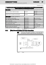
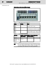
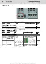
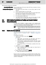


Fig.5-15:
Relay Connection
Terminal
Function
Data
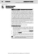
Description / suggested wiring
Parame‐
ters
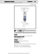
Terminal block X31 (at the top of the device)
1 K1.12 K1.2 Relay 1
N/O contact 230V AC / 24V
DC, 2A
Brake control
P434
3 K2.14 K2.2 Relay 2
Error / operative
P441
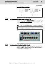
Fig.5-16:
Terminal Block X31
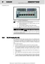
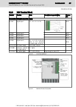
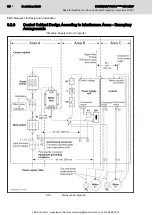
5.2.8
X35 Terminal Block
Terminal
Function
Data
Description / suggested wiring
Parame‐
ters
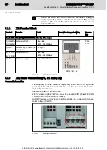
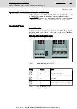
Terminal block X35 (at the front of the device)
11 VO +10V 10V reference voltage 10 V, 5 mA
The analog input controls the output fre‐
quency of the frequency converter
12 AGND/0V Reference potential of
the analog signals
0 V analog
14 AIN1
Analog input 1
0...10V, R
i
= 10kΩ, 0/4...
20mA, R
i
= 250Ω, can be
switched with DIP switch,
reference potential AGND
P400
16 AIN2
Analog input 2
P405
17 AOUT1
Analog output
0...10 V, 20 mA, reference
potential AGND
Can be used for external display or fur‐
ther processing in a secondary machine.
P418
Fig.5-17:
X35 Terminal Block
Bosch Rexroth AG
DOK-INDRV*-FCS01******-IT01-EN-P
Rexroth IndraDrive Fc Drive Controllers Frequency Converters FCS01
44/69
Instructions for Use
LSA Control S.L. www.lsa-control.com [email protected] (+34) 960 62 43 01


