
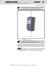


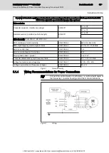
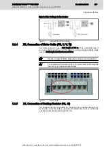
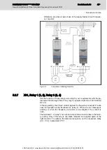

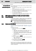


Fig.5-13:
Connection of Braking Resistor
The braking resistor heats up during operation.
●
Place the braking resistor at a sufficient distance from heat-
sensitive components.
●
Provide sufficient ventilation for the braking resistor.
●
The use of the FLR01 braking resistor is not UL/cUL-certi‐
fied.
Damage to the device due to incorrect con‐
nection!
WARNING
⇒ Exclusively connect the braking resistor between +B and -B; particularly
avoid short circuit against ground.
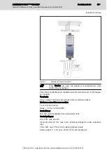
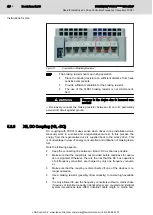
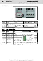
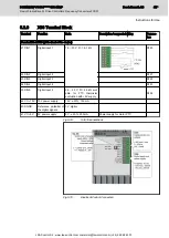
5.2.6
X5, DC Coupling (+B, -DC)
DC coupling with FCS01 makes sense when drives in one installation simul‐
taneously work in a motive and a regenerative manner. In this process, the
energy from the regenerative drive is supplied back to the motive drive. This
is of advantage in view of energy consumption and utilization of braking resis‐
tors.
Note the following aspects:
●
Keep the connecting line bB and -DC as short as possible.
●
Make sure that the coupling is not provided before readiness for opera‐
tion is signaled. Otherwise, there is the risk that the DC bus capacitors
of all frequency converters are charged by only one frequency convert‐
er.
●
Make sure that the coupling is disconnected if one of the devices is no
longer operative.
●
Use a braking resistor (possibly of low capacity) to ensure high availabil‐
ity.
●
It is only allowed to use the frequency converters without a mains choke
if devices of identical capacity (identical type) are coupled and identical
system impedances take effect (identical cable length to mains bar).
Bosch Rexroth AG
DOK-INDRV*-FCS01******-IT01-EN-P
Rexroth IndraDrive Fc Drive Controllers Frequency Converters FCS01
42/69
Instructions for Use
LSA Control S.L. www.lsa-control.com [email protected] (+34) 960 62 43 01


