

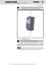


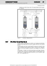

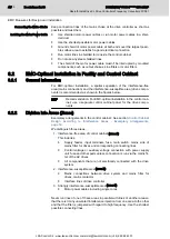


At the Bottom of the Device (Motor Output)
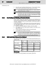
Fig.5-8:
Motor Output Jumper in Position "1"
Setting
Position
Effect
0
Operation at the IT mains
1
Standard position (condition as supplied)
2
Reduced leakage current; operation with
residual-current-operated circuit-breaker
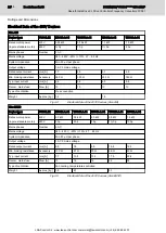
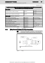
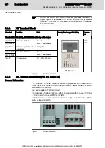
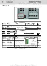
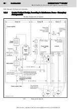
Fig.5-9:
Jumper Position at the Bottom
Operation
Position of jumper
at top of device
Position of jumper
at bottom of device
Explanation
IT mains
0
0
Residual-current-
operated
circuit-
breaker
0, 1 or 2
2
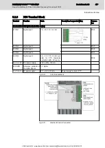
Fig.5-10:
Settings
Be aware that the specified degree of radio interference suppres‐
sion may change with the different settings. For details please
see chapter 6 "EMC Measures for Design and Installation".
Bosch Rexroth AG
DOK-INDRV*-FCS01******-IT01-EN-P
Rexroth IndraDrive Fc Drive Controllers Frequency Converters FCS01
40/69
Instructions for Use
LSA Control S.L. www.lsa-control.com [email protected] (+34) 960 62 43 01


