


Otherwise, provide a mains choke in the supply feeder of each frequen‐
cy converter.
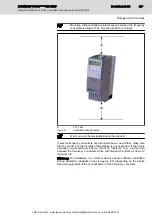
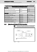
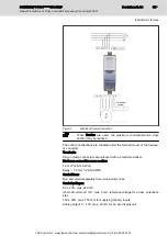
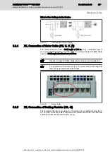
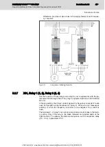
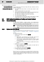
Fig.5-14:
Connection of Braking Resistor
5.2.7
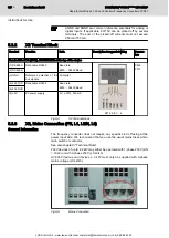
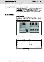
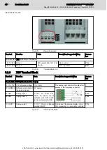
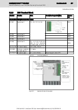
X31, Relay 1 (1, 2), Relay 2 (3, 4)
Set the function of these relays according to your requirements with the pa‐
rameters P434 through P443. They may be operated with max. 230V AC/24V
DC, 2A.
In factory setting, the closed contact signals the frequency converter's readi‐
ness for operation at the terminals 3-4 (relay 2). When an error message is
pending or when the frequency converter is de-energized, the contact is
open.
The terminals 1-2 (relay 1) can control a mechanical motor brake in the facto‐
ry setting. Only in this way is the brake released and applied again at the
right moment. To optimize the temporal sequence, set the respective delay
(0.2 - 0.3 s) in parameter P107.
DOK-INDRV*-FCS01******-IT01-EN-P
Rexroth IndraDrive Fc Drive Controllers Frequency Converters FCS01
Bosch Rexroth AG
43/69
Instructions for Use
LSA Control S.L. www.lsa-control.com [email protected] (+34) 960 62 43 01


