


English–4
3 609 929 796 • (00.07) T
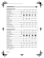
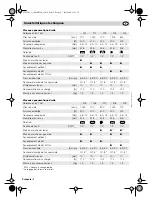
Type 0 607 461 208 / … 209
Type of Clutch
The machines have a torque depend-
ent
S-Plus clutch
that is adjustable
over a wide range. It reacts when the
torque setting is reached.
Bypassing the Disengagement
The switching off of the torque can be
bypassed by pressing the lever
10
in
order to screw into materials of differ-
ent hardness (e.g., wood with knots).
Applications:
Sheet metal screws
Wood screws
Dismantling areas
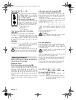
Thrust and Lever Start with S-Plus Clutch
Thrust Start
Switching on: Apply axial pressure to the tool.
Switching off:
The machine switches off automatical-
ly when the torque setting is reached.
When additional torque is required, the S-Plus can be
activated (switch-off bypass) by means of the lever
start device.
Lever Start
Switching on: Press the lever
10
. The automatic
switch-off is by-passed and an over-
load clutch reacts instead.
Switching off:
Release the lever
10
.
When the actuation lever (lever start) or the
tool pressure (thrust start) is released prema-
turely, the torque setting will not be reached!
Before performing any work on the machine it-
self, disconnect the air supply.
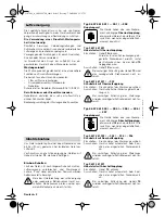
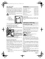
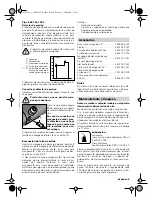
Setting the Torque
Without Unscrewing the Housing (Fig.
)
Insert the Allen key
12
into the tool holder
1
and turn
slowly until a small slot in the clutch is visible in the
opening of the housing
2
. Do not mistake the flat-
tened side of the round nut
13
for the slot. Insert the
locking hook
14
into this slot and lock the clutch. By
turning the Allen key
12
, the torque can now be ad-
justed.
Turning in the clockwise direction results in a higher
torque, in the counter clockwise direction, a lower
toque.
With Unscrewing of the Housing (Fig.
)
Unscrew the housing
2
(Left-hand threads!).
Pull off the clutch
15
. Take care that the valve pin*
does not fall out. Insert the Allen key
16
into the hex
socket of the clutch shaft. It is helpful to clamp the Al-
len key
16
in a vice.
With the 24 mm spanner placed on the round nut
13
and by turning the spanner, the spring tension can be
adjusted a detent at a time.
*For types
0 607 461 201 / … 202 / … 203 / … 204 /
… 205 /… 206 / … 207 / … 208 / … 209
Turning in the clockwise direction results in a higher
torque, in the counter clockwise direction, a lower
toque.
Begin with lower adjustment values.
Screw in the housing
2
.
Caution!
For soft bolting actions, the clutch no longer
ratchets even for low torque settings.
After the adjustment
Adapt the torque by means of trial boltings for the spe-
cific bolting action (hard, middle, soft). Check the
torque with an electronic torque measuring instrument
or a torque wrench.
For higher torques, a correspondingly greater
counter force is necessary.
With a clamping device in the area
3
, this counter
force can more easily be counteracted.
Machines that are operated with a torque greater than
4 Nm are to be used with a clamping device or an aux-
iliary handle.
Take care that the auxiliary handle or the clamping de-
vice holds the unit in a firm and secure manner.
Type 0 607 461 001 / … 201 / … 202 /
… 205 / … 206 / … 208 / … 209
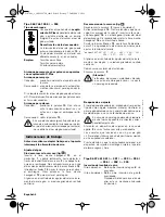
Reversing Rotational Direction
Right
rotation: Right/Left rotation button
5
not
pressed.
Left rotation:
Right/Left rotation button
5
pressed.
By turning the right/left rotation button,
the position is locked.
Working Instructions
A
B
GS7461_gb_3609929796_t.fm5 Seite 4 Freitag, 7. Juli 2000 12:25 12


