background image

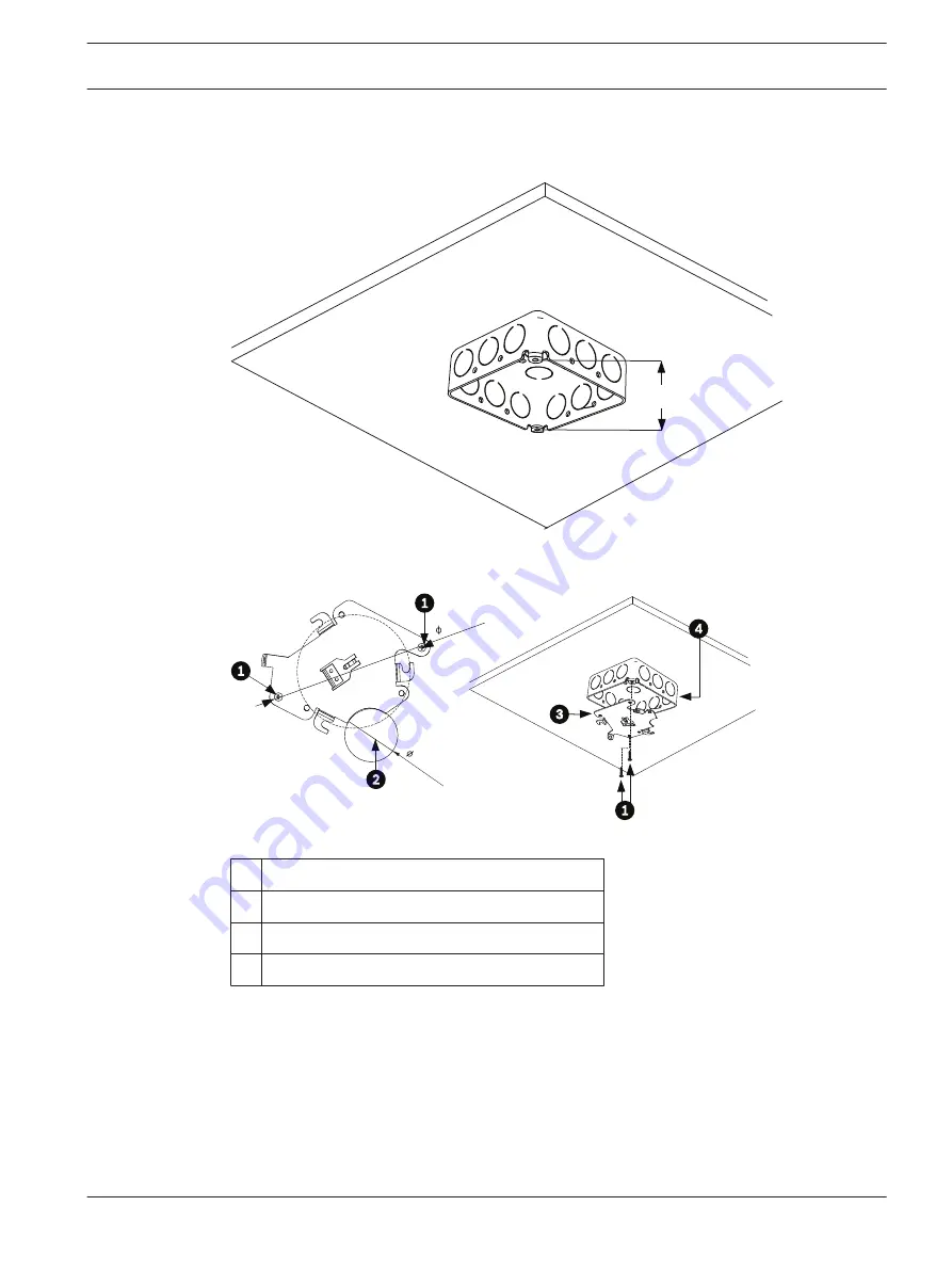
Install Junction Box
1.

Install a 4 in. gang box or square metal junction box (not supplied). Ensure junction box
and mounting screws are capable of supporting a maximum load of 11.33 kg (25 pounds).

90 mm

(3.54 in.)

Figure 4.2: Install User-supplied Junction Box

2.

Secure the mounting plate to the junction box with the user supplied hardware.

121

.16 mm

40

.0 mm

1.57

 in.

4.77 in.

Figure 4.3: Install the Mounting Plate

1

Junction Box Holes

2

Cable Hole (40 mm maximum); Crescent Shape

3

Mounting Plate

4

Junction Box

4

Skip to Installing the Camera to the Mounting Plate, page 18, to continue the installation.

See also

Preparing the Surface Mount for an Indoor Installation, page 17

Parts List, page 13

Parts List, page 13

AutoDome Junior HD Series

Installing a Surface Mount | en

17

Bosch Security Systems, Inc.

Operation Manual

2014.11 | 6.1 | F.01U.275.803

Summary of Contents for AutoDome Junior HD VJR Series

Page 1: ...AutoDome Junior HD Series VJR Series en Operation Manual ...

Page 2: ......

Page 3: ... 7 1 2 Preparing the Ceiling for Installation 30 7 1 3 Installing the Camera to the Mounting Plate 35 8 Preparing the Wiring 39 8 1 Power 39 8 2 Connecting the Power 39 8 2 1 Power Connections to Indoor Cameras 40 8 3 Ethernet Connection IP models 40 9 Audio Alarms and Relay Connections 42 9 1 Alarm Input 42 9 2 Connecting Alarms inputs 1 through 2 42 9 2 1 Connecting a Normally Open Alarm 42 9 2 ...

Page 4: ...lay Stamping 67 12 13 Advanced Mode Web Interface 68 12 14 Appearance 68 12 15 Livepage Functions 69 12 16 Logging 69 12 17 Advanced Mode Camera 70 12 18 Installer Menu 70 12 19 Encoder Profile 70 12 20 Encoder Streams 72 12 21 Privacy Masks 74 12 22 Camera Settings 74 12 23 Lens Settings 75 12 24 PTZ Settings 76 12 25 Diagnostics 78 12 26 Preposition and Tours 78 12 27 Sectors 79 12 28 Miscellane...

Page 5: ...tion 98 12 55 Advanced Mode Service 99 12 56 Maintenance 99 12 57 Licenses 100 12 58 System Overview 100 13 Keyboard Commands by Number 101 14 Troubleshooting 102 14 1 AutoDome Junior Operation and Control 103 14 2 LED Diagnostics 103 15 Preventive Maintenance 106 16 BVIP Firmware Updates 107 16 1 Upgrading the AutoDome IP or HD 107 16 2 Beginning the Firmware Update Process 107 Index 108 AutoDome...

Page 6: ...ind on the unit Do not place objects filled with liquids such as vases or cups on the unit 6 Lightning For added protection during a lightning storm or when leaving this unit unattended and unused for long periods unplug the unit from the wall outlet and disconnect the cable system This will prevent damage to the unit from lightning and power line surges 7 Control adjustment Adjust only those cont...

Page 7: ...ons 13 Replacement parts Be sure the service technician uses replacement parts specified by the manufacturer or that they have the same characteristics as the original parts Unauthorized substitutions may cause fire electrical shock or other hazards 14 Safety check Safety checks should be performed on completion of service or repairs to the unit to ensure that the unit is in proper operating condi...

Page 8: ...unit Camera grounding When mounting the camera in potentially damp environments ensure the system is grounded through the metal housing of the unit see section Connecting the Power Camera signal Protect the cable with a primary protector if the camera signal is over 140 feet in accordance with NEC800 CEC Section 60 Coax grounding Ground the cable system if connecting an outside cable system to the...

Page 9: ...et only If unable to insert the plug into the outlet contact a locally certified electrician to replace the obsolete outlet Do not defeat the safety purpose of the grounding plug Outdoor signals The installation for outdoor signals especially regarding clearance from power and lightning conductors and transient protection must be in accordance with NEC725 and NEC800 CEC Rule 16 224 and CEC Section...

Page 10: ...on helpful How to Identify and Resolve Radio TV Interference Problems This booklet is available from the U S Government Printing Office Washington DC 20402 Stock No 004 000 00345 4 INFORMATIONS FCC ET ICES modèles utilisés aux États Unis et au Canada uniquement Ce produit est conforme aux normes FCC partie 15 La mise en service est soumises aux deux conditions suivantes cet appareil ne peut pas pr...

Page 11: ... aspects of this product UL MAKES NO REPRESENTATIONS WARRANTIES OR CERTIFICATIONS WHATSOEVER REGARDING THE PERFORMANCE OR RELIABILITY OF ANY SECURITY OR SIGNALING RELATED FUNCTIONS OF THIS PRODUCT Copyright This user guide is the intellectual property of Bosch Security Systems Inc and is protected by copyright All rights reserved Trademarks All hardware and software product names used in this docu...

Page 12: ...17 735 6560 E mail technical support us bosch com Canada Telephone 514 738 2434 Fax 514 738 8480 Europe Middle East Africa Region Repair Center Telephone 31 0 76 5721500 Fax 31 0 76 5721413 E mail RMADesk STService nl bosch com Asia Region Repair Center Telephone 65 63522776 Fax 65 63521776 E mail rmahelpdesk sg bosch com Warranty and additional information For additional information and warranty ...

Page 13: ...1 mounting plate One 1 outdoor installation kit for optional VJR A3 IC54 mounting kit One 1 user manual Safety Rules To ensure safety the following warnings are specified The device must be installed and maintained by skilled technical personnel Connect the device to a power source corresponding to the indications given on the marking label Use only the attachments accessories specified by the man...

Page 14: ...3 14 15 Figure 3 1 System Configuration 1 Alarm Input sensor 12 AutoDome Junior IP or HD 2 Multiplexer 13 Network 3 RS 485 Cable 14 Computer 4 Junction Box 15 Encoder Decoder 5 AutoDome Junior 6 AutoDome Junior 7 AutoDome Junior 8 RS 485 Cable 9 Monitor 10 Keyboard 11 DVR Refer to Using the IP Interface page 47 for software and infrastructure requirements for an AutoDome Junior IP or HD installati...

Page 15: ...Notice A grounded conduit is required in order to meet the EMC Regulation Requirements AutoDome Junior HD Series Description en 15 Bosch Security Systems Inc Operation Manual 2014 11 6 1 F 01U 275 803 ...

Page 16: ...ich is visible as white lines above and below the highlight Prolonged exposure to bright lights may cause bleaching of the sensor s color filters This will be visible as colored spots in the picture and is irreversible Additional Tools Required Appropriate straight slot screwdrivers No 2 Phillips screwdriver Appropriate tool for cutting a hole in drywall or ceiling tile if applicable 4 in x 4 in J...

Page 17: ... supplied hardware 121 16 mm 40 0 mm 1 57 in 4 77 in Figure 4 3 Install the Mounting Plate 1 Junction Box Holes 2 Cable Hole 40 mm maximum Crescent Shape 3 Mounting Plate 4 Junction Box 4 Skip to Installing the Camera to the Mounting Plate page 18 to continue the installation See also Preparing the Surface Mount for an Indoor Installation page 17 Parts List page 13 Parts List page 13 AutoDome Juni...

Page 18: ...user supplied ground to junction box 4 Connect the mating connectors with the flying leads to the user supplied wiring see Preparing the Wiring page 39 for wiring information 5 Unlock the single safety locking screw on the base of the unit using the user supplied Allen wrench Figure 4 4 Unlock Safety Locking Screw 6 Plug the matching connectors from the camera into the mating connectors from the c...

Page 19: ...he vertical tab on the plate item 1 below into the recessed slot on the top of the camera dome Item 3 to the right of the safety locking screw item 2 Note Do not loosen the three brass buttons item 4 These brass buttons engage the slotted tabs item 5 on the mounting plate AutoDome Junior HD Series Installing a Surface Mount en 19 Bosch Security Systems Inc Operation Manual 2014 11 6 1 F 01U 275 80...

Page 20: ...n total of three on housing 5 Slotted Tab total of three on mounting plate 3 Rotate the camera approximately 15 degrees in a clockwise direction to lock firmly into place as shown in the next illustration 20 en Installing a Surface Mount AutoDome Junior HD Series 2014 11 6 1 F 01U 275 803 Operation Manual Bosch Security Systems Inc ...

Page 21: ...e safety locking screw with the user supplied locking torx wrench T 10 See also Preparing the Surface Mount for an Indoor Installation page 17 AutoDome Junior HD Series Installing a Surface Mount en 21 Bosch Security Systems Inc Operation Manual 2014 11 6 1 F 01U 275 803 ...

Page 22: ...effect which is visible as white lines above and below the highlight Prolonged exposure to bright lights may cause bleaching of the sensor s color filters This will be visible as colored spots in the picture and is irreversible Additional Tools Required Appropriate straight slot screwdrivers No 2 Phillips screwdriver Appropriate tool for cutting a hole in drywall or ceiling tile if applicable T 10...

Page 23: ...x 8 Secure with the appropriate user provided SEMS screws that have an integral lock washer to dig through the paint and ensure an electrical ground connection to the arm housing or ground lug Notice The metal junction box and mounting surface must be capable of supporting a maximum load of 11 33 kg 25 pounds AutoDome Junior HD Series Installing a Wall Mount en 23 Bosch Security Systems Inc Operat...

Page 24: ...pe 2 Mounting Screws for Dome Cap 2 Route wires on side of mounting plate with crescent shaped cut out Ref 2 page 24 3 Attach grounding wire from unit to the mounting cap see below 4 Attach user supplied ground to junction box 5 Connect the mating connectors with the flying leads to the user supplied wiring see the Preparing the Wiring page 39 for wiring information 6 Unlock the single safety lock...

Page 25: ...cking Screw 7 Plug the matching connectors from the camera into the mating connectors from the ceiling AutoDome Junior HD Series Installing a Wall Mount en 25 Bosch Security Systems Inc Operation Manual 2014 11 6 1 F 01U 275 803 ...

Page 26: ...plate item 1 below into the recessed slot on the top of the camera dome Item 3 to the right of the safety locking screw item 2 Note Do not loosen the three brass buttons item 4 These brass buttons engage the slotted tabs item 5 on the mounting plate 26 en Installing a Wall Mount AutoDome Junior HD Series 2014 11 6 1 F 01U 275 803 Operation Manual Bosch Security Systems Inc ...

Page 27: ...late 2 Locking Screw 3 Recessed Slot on dome housing 4 Brass Button total of three on housing 5 Slotted Tab total of three on mounting plate AutoDome Junior HD Series Installing a Wall Mount en 27 Bosch Security Systems Inc Operation Manual 2014 11 6 1 F 01U 275 803 ...

Page 28: ...unting buttons Figure 5 7 Attach Dome to Mounting Plate 1 Secure the safety locking screw with the user supplied locking torx wrench T 10 2 Pull excess wire back into the mount tube 3 Confirm that the housing is electrically grounded 28 en Installing a Wall Mount AutoDome Junior HD Series 2014 11 6 1 F 01U 275 803 Operation Manual Bosch Security Systems Inc ...

Page 29: ...Installing a Recessed Mount 6 AutoDome Junior HD Series Installing a Recessed Mount en 29 Bosch Security Systems Inc Operation Manual 2014 11 6 1 F 01U 275 803 ...

Page 30: ...effect which is visible as white lines above and below the highlight Prolonged exposure to bright lights may cause bleaching of the sensor s color filters This will be visible as colored spots in the picture and is irreversible Tools Supplies Required Appropriate straight slot screwdrivers No 2 Phillips screwdriver Appropriate tool for cutting a hole in drywall or ceiling tile if applicable T 10 T...

Page 31: ... applications must be routed through a grounded conduit 3 Drill a fifth hole maximum of 20 mm 79 in in the center of the four hole pattern used to mount the flange Use this hole to feed the wires through the mount Notice The fasteners and mounting surface must be capable of supporting a maximum load of 11 33 kg 25 pounds 1 Pull the wires from the pipe starting at the flange end AutoDome Junior HD ...

Page 32: ...Figure 7 3 Attach Pendant Pipe Mount to Ceiling 32 en Installing a Pipe Mount AutoDome Junior HD Series 2014 11 6 1 F 01U 275 803 Operation Manual Bosch Security Systems Inc ...

Page 33: ... Camera 2 Attach user supplied ground lug 3 Align holes of mounting plate supplied with dome with dome mounting cap and attach with the three 3 screws supplied Figure 1 9 AutoDome Junior HD Series Installing a Pipe Mount en 33 Bosch Security Systems Inc Operation Manual 2014 11 6 1 F 01U 275 803 ...

Page 34: ...34 en Installing a Pipe Mount AutoDome Junior HD Series 2014 11 6 1 F 01U 275 803 Operation Manual Bosch Security Systems Inc ...

Page 35: ...ent shaped cut out 2 Attach grounding wire from unit to mounting cap 3 Attach user supplied ground to junction box 4 Connect the mating connectors with the flying leads to the user supplied wiring see the Preparing the Wiring page 39 for wiring information 5 Unlock the single safety locking screw on the base of the unit using the user supplied Allen wrench 7 1 3 AutoDome Junior HD Series Installin...

Page 36: ...haped cut out 8 Attach the camera to the mounting plate by inserting the vertical tab on the plate item 1 below into the recessed slot on the top of the camera dome Item 3 to the right of the safety locking screw item 2 Note Do not loosen brass mounting buttons 36 en Installing a Pipe Mount AutoDome Junior HD Series 2014 11 6 1 F 01U 275 803 Operation Manual Bosch Security Systems Inc ...

Page 37: ...late 2 Locking Screw 3 Recessed Slot on dome housing 4 Brass Button total of three on housing 5 Slotted Tab total of three on mounting plate AutoDome Junior HD Series Installing a Pipe Mount en 37 Bosch Security Systems Inc Operation Manual 2014 11 6 1 F 01U 275 803 ...

Page 38: ...e 7 7 Attach Dome to Mounting Plate 4 Secure the safety locking screw with the user supplied locking torx wrench T 10 1 Pull excess wire back into the mount tube 2 Confirm that the housing is electrically grounded 38 en Installing a Pipe Mount AutoDome Junior HD Series 2014 11 6 1 F 01U 275 803 Operation Manual Bosch Security Systems Inc ...

Page 39: ...r Supply to AutoDome Junior HD Connecting the Power The AutoDome Junior HD is available as an indoor model only Power to the camera in all indoor models is supplied either via a single 24 VAC isolated power connector or via a Power over Ethernet PoE IEEE 802 3at class 4 connection using the existing CAT 5E Ethernet cable Warning The indoor AutoDome Junior IP or HD camera models can accept power fr...

Page 40: ...ther end 2 Connect one lead of the 24 VAC power source to the black wire 3 Connect the other lead of the 24 VAC power source to the red wire 4 Connect the green earth ground cable to a suitable grounded conduit Ethernet Connection IP models The AutoDome Junior HD connects to a 10 Base T 100 Base TX network either directly or via a switch Both video and control are transmitted over a standard TCP I...

Page 41: ...AT 5E or CAT 6 Ethernet Maximum Distance 100 m 328 ft Bandwidth 10 Base T 100 Base TX PoE indoor models only IEEE 802 3at class 4 standard Terminal Connector RJ45 Female AutoDome Junior HD Series Preparing the Wiring en 41 Bosch Security Systems Inc Operation Manual 2014 11 6 1 F 01U 275 803 ...

Page 42: ... Ground The table below summarizes the size and distance wires Wire Size Maximum Distance AWG mm feet meters 22 0 644 500 152 4 18 1 024 800 243 8 Table 9 1 Alarm Wire Guide You wire alarms either Normally Open N O or Normally Closed N C and must program the alarm inputs N O the default or N C through the AutoDome Junior main menu Connecting Alarms inputs 1 through 2 You can configure alarms 1 thr...

Page 43: ...onnecting a Normally Closed Alarm 4 Connect the alarm to the appropriate input 1 through 2 and ground at the AutoDome Junior Figure 9 3 N C Normally Closed Connections Ref User Contact Dome Color 1 Normally Closed Alarm In 1 or Alarm In 2 Ref 3 Brown IN 1 or Orange IN 2 2 Common Ground Ref 4 Green 4 From the AutoDome Junior HD Settings page select Interface Alarm Inputs Refer to Configuring the Au...

Page 44: ...tive voltage between 5 and 32 V to complete the circuit with a maximum voltage rating of 32 VDC 150 ma 1 Connect the appropriate stripped wire to the open collector of the transistor s white wire 2 Connect the appropriate stripped wire to the ground GND connector Audio Cables The AutoDome Junior is capable of receiving line input audio signals and transmitting it over a network The audio signal is...

Page 45: ...nternal gain level adjustment is available Wire Specifications Wire Type Coax3 recommended Distance 10 m 33 ft Gage 22 AWG Shield Bare copper braid 95 coverage Center conductor Stranded bare copper AutoDome Junior HD Series Audio Alarms and Relay Connections en 45 Bosch Security Systems Inc Operation Manual 2014 11 6 1 F 01U 275 803 ...

Page 46: ...r power on there is a ten 10 second pause before the dome starts its homing phase During the homing phase the camera pans left and right and tilts up and down It also adjusts the lens focus The entire homing phase lasts approximately 20 seconds and ends with a splash screen If you are using an AutoDome Junior IP or HD model refer to Using the IP Interface page 47 Warning Before powering the dome o...

Page 47: ...s page 107 for firmware upgrade instructions Overview of Features The AutoDome Junior HD module includes the following functionality Function Description Video Encoding The camera uses the H 264 compression standards and ensures that the data rate remains low even with high image quality and can also be adapted to local conditions within wide limits Streaming Encodes multiple data streams simultan...

Page 48: ...address of the unit In Windows Vista deactivate protected mode on the Security tab under Internet Options In Windows 7 deactivate protected mode on the Security tab under Internet Options You can find notes on using Microsoft Internet Explorer in the online Help in Internet Explorer If you choose to use a computer running Microsoft Internet Explorer or any of the Bosch software the computer must c...

Page 49: ...e Junior HD System Configuration 1 AutoDome Junior HD 2 IP Connection 3 Network Switch 4 Computer Notice You can also use the Bosch Configuration Manager utility to configure the network settings for an AutoDome Junior IP or HD camera Go to www boschsecurity com to download the Configuration Manager software and Operating Manual Configuring the AutoDome Junior HD Camera To operate the camera in yo...

Page 50: ... IP server Notice Contact your local network administrator for a valid IP address Subnet Mask and a Gateway IP Address Using the Configuration Manager Configuration Manager is an optional network utility provided on the Bosch Security Systems Web site Use the Configuration Manager Manual to make any configuration changes Notice Depending on the PC network security settings the user may have to add...

Page 51: ...l network administrator Notice Click the Help on this page link if you need more information 8 Click the Set button to save the settings 9 Launch another instance of Microsoft Internet Explorer AutoDome Junior HD Series Using the IP Interface en 51 Bosch Security Systems Inc Operation Manual 2014 11 6 1 F 01U 275 803 ...

Page 52: ... The frame might show artefacts due to decoding errors If subsequent frames reference this corrupted frame they might also show decoding errors as well but won t be marked with the decoding error icon Alarm flag set on media item Communication error Any kind of communication error is visualized by this icon Cause can be a connection failure to the storage medium a protocol violation with a sub com...

Page 53: ...h the discovery has not yet reached The gap will automatically be replaced by the true video as soon as the correct information is available Maximum Number of Connections If you do not connect the unit may have reached its maximum number of connections Depending on the unit and network configuration each AutoDome Junior IP can have up to 25 Web browser connections or up to 50 connections via the B...

Page 54: ...ontrol camera functions pan tilt zoom focus and iris navigate through on screen menus and to view preset shots Not applicable with the AutoDome Junior HD Fixed camera Reference Description Reference Description 1 Tilts the camera up 8 Focus far 2 Tilts the camera down 9 Focus near 3 Pans the camera to the left 10 Iris close 4 Pans the camera to the right 11 Iris Open l 5 Pans and tilts the camera ...

Page 55: ... online help Triggering Relay You can switch connected units using the relays in the AutoDome Junior for example lights or door openers 4 To activate this click the icon for the relay next to the video image The icon will be red when the relay is activated System Log Event Log The System Log field contains information about the operating status of the AutoDome Junior IP and the connection You can ...

Page 56: ... 0 9 3 Show a preset shot 4 Set a preset shot 5 Initiates a command 6 Deletes a number in the Command Number field 7 Used to select a menu item 8 Stops a command To Enter a Keyboard Control Command 1 Place the cursor in the Command Number field 2 Click the desired command number via the on screen keypad 3 Click either the Aux On or the Aux Off button to initiate or stop the command 4 If the comman...

Page 57: ...ctional control in the View Control tab Tour A Tour B Click one of these buttons to start a recorded guard tour A Recorded Tour saves all manual camera movements made during the recording including its rate of pan tilt and zoom speeds and other lens setting changes Refer to PTZ Settings page 76 to program a recorded tour To stop a tour click a directional control in the View Control tab Commission...

Page 58: ...age location depends on the configuration of the AutoDome Junior HD Recording Video Sequences You can save sections of the video sequence currently shown on the Livepage on your computer s hard drive The icon for recording video sequences is only visible if the unit is configured to enable this process 4 Click the icon to start recording The storage location depends on the configuration of the Aut...

Page 59: ...y Controlling a Playback You will see a time bar below the video image for quick orientation A green arrow above the bar indicates the position of the image currently being played back within the sequence The time bar offers various options for navigation Red bars indicate the points in time where alarms were triggered Drag the green arrow to navigate to these points quickly 1 You can change the t...

Page 60: ... previous bookmark Set bookmark Jump to the following bookmark Jump to the previous bookmark Set bookmark Jump to the following bookmark Notice Bookmarks are only valid while you are in the Recordings page they are not saved with the sequences As soon as you leave the page all bookmarks are deleted 60 en Using the IP Interface AutoDome Junior HD Series 2014 11 6 1 F 01U 275 803 Operation Manual Bo...

Page 61: ... Junior HD memry so they are not lost even if the power fails Starting Configuration 4 Click the SETTINGS link in the upper section of the window The Web browser opens a new page with the configuration menu Navigation 1 Click one of the menu items in the left window margin The corresponding submenu is displayed 2 Click one of the entries in the submenu The Web browser opens the corresponding page ...

Page 62: ...n all higher authorization levels are also protected with a password If a live password is assigned for example a service and a user password must also be set When assigning passwords you should therefore always start from the highest authorization level service and use different passwords Confirm password In each case enter the new password a second time to eliminate typing mistakes Notice A new ...

Page 63: ...se these applications the DHCP server must support the fixed assignment between IP address and MAC address and must be appropriately set up so that once an IP address is assigned it is retained each time the system is rebooted IP address Enter the desired IP address for the AutoDome Junior HD in this field The IP address must be valid for the network Subnet mask Enter the appropriate subnet mask f...

Page 64: ...m parallel to the video data and so increase the network load The audio data are encoded according to G 711 and require an additional bandwidth of approx 80 kbps for each connection If you do not want any audio data to be transmitted select Off Line In You can set the line input gain Make sure that the display does not go beyond the green zone during modulation Basic Mode Recording You can record ...

Page 65: ... or click the X icon to delete all characters 5 Now click the OK button to apply the selected characters to the second line of the Camera 1 parameters The window will close Initiator extension You can attach your own text to the initiator name of the AutoDome Junior HD to make the unit easier to identify in large iSCSI systems This text is added to the initiator name separated from it by a full st...

Page 66: ...aylight saving time The internal clock can switch automatically between normal and daylight saving time DST The unit already contains the data for DST switch overs up to the year 2018 You can use these data or create alternative time saving data if required Notice If you do not create a table there will be no automatic switching When changing and clearing individual entries remember that two entri...

Page 67: ...elds enter the values for the desired position Time stamping This field sets the position of the time overlay It can be displayed at the Top at the Bottom or at a position of your choice that you can then specify using the Custom option Or it can be set to Off for no overlay information 1 Select the desired option from the list 2 If you select the Custom option additional fields are displayed wher...

Page 68: ...e language to meet your requirements If necessary you can replace the manufacturer s logo top right and the product name top left in the top part of the window with individual graphics Notice You can use either GIF or JPEG images The file paths must correspond to the access mode for example C Images Logo gif for access to local files or http www mycompany com images logo gif for access via the Int...

Page 69: ...or Show VCA trajectories When video content analysis VCA is activated check this item to show additional information that traces the path of objects Show VCA metadata When video content analysis VCA is activated additional information is displayed in the live video stream For example in Motion mode the sensor areas for motion detection are marked Show event log The event messages are displayed alo...

Page 70: ... window Use the View Control arrow keys and the zoom keys to establish the desired view Notice The View Control window is disabled 15 minutes after you open the window If the View Control window is disabled you must close the window then re open to resume setting the camera position and zoom level Encoder Profile For the video signal encoding you can select a code algorithm and you can change the ...

Page 71: ...s outside the permitted range for a particular parameter the nearest permitted value will be substituted when the settings are saved Profile name You can enter a new name for the profile here The name is then displayed in the list of available profiles in the Profile name field Target data rate You can limit the data rate for the AutoDome Junior HD to optimize utilization of the bandwidth in your ...

Page 72: ...atically adjusts the quality to the settings for the P frame video quality Alternatively you can use the slide control to set a value between 9and51 The value 9 represents the best image quality with if necessary a lower frame refresh rate depending on the settings for the maximum data rate A value of 51 results in a very high refresh rate and lower image quality P frame Quality This setting allow...

Page 73: ...ach stream Notice If you select H 264 MP 720p30 60 Fixed or H 264 MP 1080p Fixed as the first stream you can select only Copy of Stream 1 as an option for stream 2 Default profile Select one of the following profiles for each stream HD high quality low latency High resolution 2 Low bandwidth DSL ISDN 2B ISDN 1B Modem GSM Refer to Encoder Profile page 70 for more details about each stream Preview C...

Page 74: ... choose to hide all masks you must enable each enable each individual mask to show the mask in the scene Camera Settings White Balance Adjusts the color settings to maintain the quality of the white areas of the image ATW allows the camera to continuously adjust color reproduction Indoor white balance tracking for indoor use Outdoor white balance tracking for outdoor use AWB Hold places the ATW on...

Page 75: ...mizes the video level for the selected area of the image Parts outside this area may be underexposed or overexposed Select On to optimize the video level for the central area of the image The default setting is Off Stabilization Turns on video stabilization Night Mode Selects night mode B W to enhance lighting in low light scenes Select from the following options Monochrome Forces the camera to st...

Page 76: ...ype a value between 1 and 15 inclusive The default setting is 8 Iris Speed Controls how fast the Iris will adjust the opening according to the illumination of the scene Type a value between 1 and 10 inclusive The default setting is 5 Maximum Zoom Speed Controls the zoom speed The default setting is Fast Zoom Polarity Capability to reverse the operation of the zoom button on the controller Normal d...

Page 77: ...certain objects such as a tree or a flag swaying in the wind in a confined area after the specified number of seconds Settings range from 5 to 120 The default is 30 Auto pan left limit Sets the left Auto Pan limit of the camera Use the preview window to move the camera to the left pan limit and click the button The camera will not move past this limit when in Auto Pan Between Limits mode AUX 2 ON ...

Page 78: ...igate to the scene that you want to define as a preposition Click the View Control link Use the PTZ controls to move the camera into position 2 Click the Add scene button to define the preposition 3 Select a number for the scene from 1 to 64 4 Type an optional name for the scene up to 20 characters long 5 Click OK to save the scene to the Preposition list 6 The asterisk to the left of the scene na...

Page 79: ...o the right of the sector number 2 Type a title for the sector up to 20 characters long 3 To blank the sector click the check box to the right of the sector title Miscellaneous Address Allows the appropriate dome to be operated via the numerical address in the control system Type a number between 0000 and 9999 inclusive to identify the camera Logs To save the log file information 1 Click Download ...

Page 80: ...Recording Manager Control all recording when accessing an iSCSI system This is an external program for configuring recording tasks for video servers For further information please contact your local customer service at Bosch Security Systems Inc Device manager If you activate the VRM option in this screen the VRM Video Recording Manager will manage all recording and you will not be able to configu...

Page 81: ...ox in the Rec 1 or Rec 2 to specify which data stream should be recorded on the storage media selected Rec 1 stores Stream 1 Rec 2 stores Stream 2 This means that you can record the standard data stream on a hard drive and record alarm images on the mobile CF card for example 5 Check the boxes for the Overwrite older recordings option to specify which older recordings can be overwritten once the a...

Page 82: ... of storage capacity as soon as a time gap for alarm recording begins a recording is continuously made on one segment which is the size of a complete alarm sequence pre and post alarm time This segment functions in a similar manner to a ring buffer and is overwritten until an alarm is actually triggered Then recording occurs on the segment only for the duration of the preset post alarm time and a ...

Page 83: ...ds with the available memory capacity A rule of thumb for the memory requirement is as follows 1 GB per hour retention time with 4CIF for complete frame rate and high image quality Retention time Enter the required retention time in hours or days for each recording Recording 1 corresponds to Stream 1 Recording 2 corresponds to Stream 2 Recording Schedule The recording scheduler allows you to link ...

Page 84: ...a profile and then the Rename button 2 Enter your chosen name and then click the Rename button again Activating the Recording After completing configuration you must activate the recording scheduler and start the recording The configuration can be modified at any time You can stop the recording activity at any time and modify the settings 1 Click the Start button to activate the recording schedule...

Page 85: ...s follows 1 Select 10 from the Number of destination IP address list field 2 Enter the address 0 0 0 0 in the Destination IP address field 3 Enter your chosen password in the Destination password field 4 Define this password as the user password for all remote stations to which a connection is to be possible Notice If you enter the destination IP address 0 0 0 0 for destination 10 this address wil...

Page 86: ... parameter Notice Please note that the SSL encryption must be activated and configured at both ends of a connection This requires the appropriate certificates to be uploaded onto camera You can activate and configure encryption of the media data video and metadata on the Encryption page see Encryption page 98 Auto connect Select the On option to automatically re establish a connection to one of th...

Page 87: ... new profile name in the field 2 Click the icon again The new profile name is saved Alarm status The alarm status is displayed here for information purposes This means you can check the effects of your settings immediately Analysis type Select the required analysis algorithm By default only MOTION is available this offers a motion detector and essential recognition of tampering Notice Additional a...

Page 88: ...e selected The video image is subdivided into 858 square fields Each of these fields can be activated or deactivated individually If you wish to exclude particular regions of the camera s field of view from monitoring due to continuous movement by a tree in the wind etc the relevant fields can be deactivated 1 Click Select Area to configure the sensor fields A new window will open 2 If necessary c...

Page 89: ...d trigger an alarm Scene too bright Activate this function if tampering associated with exposure to extreme light for instance shining a flashlight directly on the lens should trigger an alarm The average brightness of the scene provides a basis for recognition Scene too dark Activate this function if tampering associated with covering the lens for instance by spraying paint on it should trigger a...

Page 90: ... the basis of the signal visible in the graphic You can set the threshold using the slide control or alternatively you can move the white line directly in the graphic using the mouse Sensitivity You can use this setting to adapt the sensitivity to the sound environment You can effectively suppress individual signal peaks A high value represents a high level of sensitivity Signal Ranges You can exc...

Page 91: ...ditor Caution Editing scripts on this page overwrites all settings and entries on the other alarm pages This procedure cannot be reversed In order to edit this page you must have programming knowledge and be familiar with the information in the Alar Task Script Editor document As an alternative to the alarm settings on the various alarm pages you can enter your desired alarm functions in script fo...

Page 92: ...d Commands by Number page 101 for a list of valid commands Note Only commands 1 8 18 20 43 60 80 86 are supported Support for the remaining commands is scheduled for a future release Shot defines a preset scene from shot 1 64 4 Click Set to save and to activate the alarm rules Advanced Mode Interfaces Alarm Inputs Select the type of input for each physical alarm Select from either N O Normally Ope...

Page 93: ...y icon Furthermore in the Forensic Search program you can use the name as a filter option for quick search through the recordings Caution Do not use any special characters for example in the name Special characters are not supported by the system s internal recording management and may therefore result in the Player and Archive Player programs being unable to play back the recording Trigger Relay ...

Page 94: ...x is the part of the address where the bits have fixed values or are the bits that define a subnet Gateway address If you want the unit to establish a connection to a remote location in a different subnet enter the IP address of the gateway here Otherwise leave the box blank 0 0 0 0 DNS server address 1 DNS server address 2 The camera is easier to access if the unit is listed on a DNS server If yo...

Page 95: ...mission you must select the Off option to deactivate Telnet support The unit will then no longer be accessible using the Telnet protocol Interface mode ETH If necessary select the Ethernet link type for the ETH interface Depending on the unit connected it may be necessary to select a special operation type Network MSS Byte You can set the maximum segment size for the IP packet s user data This giv...

Page 96: ...tion via the network is not enabled until the Identity and Password parameters have been set and successfully authenticated Identity Enter the name that the RADIUS server is to use for identifying the camera Password Enter the password that is stored in the RADIUS server RTSP port If necessary select a different port for the exchange of the RTSP data from the list The standard RTSP port is 554 Sel...

Page 97: ...enabled network The network must support group IP addresses and the Internet Group Management Protocol IGMP V2 The address range is from 225 0 0 0 to 239 255 255 255 The multicast address can be the same for multiple streams However it will be necessary to use a different port in each case so that multiple data streams are not sent simultaneously using the same port and multicast address Notice Th...

Page 98: ...tly set Example the file snap011005_114530 jpg was stored on October 1 2005 at 11 45 and 30 seconds Posting interval Enter the interval in seconds at which the images will be sent to an FTP server Enter zero if you do not want any images to be sent FTP server IP address Enter the IP address of the FTP server on which you wish to save the JPEG images FTP server login Enter your login name for the F...

Page 99: ...he full path of the file to upload or click Browse to select the required file 2 Make certain that the file to be loaded comes from the same unit type as the unit you want to configure 3 Next click Upload to begin transferring the file to the unit The progress bar allows you to monitor the transfer Once the upload is complete the new configuration is activated The time remaining is shown by the me...

Page 100: ... modules Notice The activation key cannot be deactivated again and is not transferable to other units System Overview The data on this page are for information purposes only and cannot be changed Keep a record of this information in case technical assistance is required Notice You can select all required text on this page with the mouse and copy it to the clipboard with the Ctrl C key combination ...

Page 101: ...layback Tour A Activate Deactivate On Off 52 Playback Tour B Activate Deactivate Y On Off 60 On Screen Display On enable Off disable Y On Off 80 Digital Zoom Lock Turns digital zoom on and off Y On Off 86 Sector Blanking Enables Disables Sector Blanking Y On Off 87 Privacy Masking On enabke Off disable On Off 90 Command Lock Unlock On lock on Off Lock off On Off 100 Record Tour A On start recordin...

Page 102: ...irty If so clean the lens with a soft clean cloth The contrast on the screen is too weak Adjust the contrast feature of the monitor Is the camera exposed to strong light If so change the camera position The image on the screen is flickers Does the camera face directly into the sun or fluorescent lighting If so reposition camera The image on the screen is distorted Is the power frequency set proper...

Page 103: ...elect UDP from the Video Transmission drop down list Then click Set Video is distorted AutoDome Junior HD Navigate to the SETTINGS page Click the Advanced Link then click the Camera link located in the left pane of the Settings window Click the Installer Menu located under the Camera link Select either 50 or 60 Hz from the Frequency pull down list LED Diagnostics Use the following illustration to ...

Page 104: ...ing data Off No network activity 2 Red Network Link On Link is active Off Link failure 3 Bi color LED Green Red Power IP Board Green On IP board is running Red On IP board is booting 104 en Troubleshooting AutoDome Junior HD Series 2014 11 6 1 F 01U 275 803 Operation Manual Bosch Security Systems Inc ...

Page 105: ...to the IP board Green Flashing IP board is transmitting video Red Flashing IP board is resetting AutoDome Junior HD Series Troubleshooting en 105 Bosch Security Systems Inc Operation Manual 2014 11 6 1 F 01U 275 803 ...

Page 106: ...unting hardware is secure When cleaning the dome bubble heed these warning Do not use alcohol based solutions to clean the bubble This will cause the bubble to cloud and over time cause stress aging which makes the bubble brittle Do not use abrasive or highly alkaline cleaners on the bubble Do not scrape the bubble with razor blades or other sharp instruments Do not use Benzene Gasoline Acetone or...

Page 107: ...P or HD through a Local Area Network LAN You cannot however update the AutoDome IP or HD through a Wide Area Network WAN or via the Internet Beginning the Firmware Update Process Use this procedure to connect to your AutoDome IP or HD and to navigate to the Firmware Update page 1 Launch Internet Explorer and type the IP address for the AutoDome IP or HD in the Address bar and click Go Internet Exp...

Page 108: ...l 88 commands reset reset configuring IP AutoDome reset AutoDome IP reset 52 configuration download 99 Configuration Manager 50 configuration mode 61 connect on alarm 84 connectors pin mating 40 control signals 69 controlling image area 55 Controlling a Playback 59 D date 66 date format 66 daylight saving time 66 default profile 72 default recording profile 82 default VCA profile 86 deleting recor...

Page 109: ...rking IP address 49 alarm 55 audio 103 gateway address gateway address networking gateway address 50 subnet mask subnet mask networking subnet mask 50 system requirements 48 IP address 94 IP protocol TCP IP TCP IP networking TCP IP networking IP IP module 47 IPv4 94 IPv6 94 iSCSI settings 80 J JPEG posting 98 JPEG posting interval 98 JPEG files JPEG 48 K keyboard commands 56 keyboard commands comm...

Page 110: ...figuring IP AutoDome network settings 50 non supervised alarms alarm inputs non supervised 42 number of connections 53 P password 53 62 65 66 Playback button 59 port 94 97 port IP port networking port 50 post alarm profile 82 post alarm time 82 pre alarm time 82 prefix length 94 preset shot commands preset shot 56 processor load 58 processor load indicator 58 product name 68 profile configuration ...

Page 111: ...time 62 66 67 time server 62 67 IP address 63 protocol 62 time server IP address 67 time server protocol 67 time signal 62 67 time zone 66 TLS 95 tour guard 77 recorded 77 transmission protocol 85 94 traps 96 TTL 98 U UDP 85 94 UDP IP UDP 103 UDP networking UDP protocol UDP protocol IGMP V2 IGMP V2 networking IGMP V2 47 unicast 97 unit date 66 unit identification 61 unit name 61 unit time 62 66 us...

Page 112: ......

Page 113: ......

Page 114: ...Bosch Security Systems Inc 850 Greenfield Road Lancaster PA 17601 USA www boschsecurity com Bosch Security Systems Inc 2014 Bosch Sicherheitssysteme GmbH Robert Bosch Ring 5 85630 Grasbrunn Germany ...

Reviews: