8
Keyboard Diagrams
KBD-1010
1.
Power Button
Power on / Power off the keyboard
2.
12V DC Power Port, wide range input tolerance from 5V-48VDC
Connect the supplied DC power adaptor and cord
3.
Firmware Interface Button
Engages firmware update mode on the keyboard
4.
Kensington Security slot
Use a lock to physically secure the keyboard in place
5.
Tally / Contact (GPI I/O connector)
Tally control interface
6.
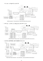
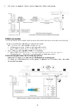
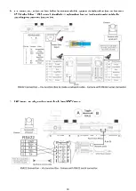
RS232 interface / RJ-45 port
Connect RS232 adapter
7.
IP Interface / RJ-45 port
Connect the keyboard to a network or a PoE switch for power supply
8.
RS422 (B) interface, use for RS485 as well / RJ-45 port
Connect an RS422 adapter to control up to 7 daisy-chained RS422 cameras (Group A)
9.
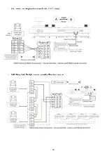
RS422(A) interface,
a.
In PTZ Controller Mode, use for RS485 as well / RJ-45 port
Connect an RS422 adapter to control up to 7 daisy-chained RS422 cameras (Group B)
b.
In Video Router Switch Mode, control connection interface / RJ-45 port
Connect to video matrix, to control video switching via keyboard
10.
Firmware Upgrade USB port
Summary of Contents for KBD-1010
Page 17: ...17 ...
Page 19: ...19 ...
Page 20: ...20 ...
Page 21: ...21 ...
Page 23: ...23 ...
Page 24: ...24 ...
Page 25: ...25 ...
Page 26: ...26 IP Control Use ONVIF IP Control Use VISCA OVER IP Control ...
Page 50: ...50 Dimensions Unit mm KBD 1010 Junction Box ...
Page 51: ...51 www bolintechnology com 2082 TECHNOLOGY LLC dba BOLIN TECHNOLOGY ...


