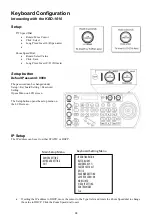
36
o
P/T Reset
– Reset the selected camera
o
Power
– Power off the selected camera
o
Mute
– Mute the audio from the selected camera
o
Picture Freeze
– Freeze the image of the selected camera
o
Picture Flip
– Flip the image of the selected camera
o
Picture LR Reverse
– Invert the L/R (pan direction) of the selected camera
o
None – No function will be assigned to the key
•
Exit
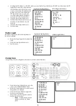
Factory Default
Clear all keyboard settings, and restore factory
default
•
From the Keyboard Setup Menu, select
FACTORY DEFAULT
•
Select Yes
NOTE: DO NOT move the Joystick nor the
Zooming Seesaw and leave them at original
position while the FACTORY DEFAULT is
processing.
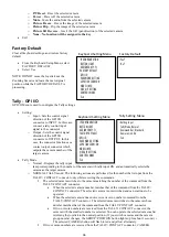
Tally - GPI I/O
GPI I/O Menu is used to configure the Tally settings
•
Setting:
o
Input - Sets the control signal
direction of the GPI I/O
connector to INPUT. In this case,
connect a tally control input
signal to the connector
o
Output - Sets the control signal
direction of the GPI I/O
connector to OUTPUT. In this
case, the connector functions as a
contact output connector which
outputs the camera number of the
target camera.
•
Tally Mode
o
Normal - Displays the tally input
lamp corresponding to the number of the camera with tally input ON, and automatically selects the
camera as the target camera.
o
NORMAL TALLY mode: The following actions are performed for the number that is input from the
TALLY/ CONTACT connector only while receiving the commands.
▪
The selected camera switches to the camera matching the number of the command from the
TALLY/CONTACT connector.
•
When the selected camera number matches that of the command from the TALLY/
CONTACT connector: The selected camera is not switched and can continue to be
operated.
•
When the selected camera does not receive its own number command from the
TALLY/CONTACT connector: The selected camera switches to the camera whose
number matches that of the command from the TALLY/CONTACT connector.
•
If two or more numbers are received from the TALLY/ CONTACT connector, the
camera with the smallest number is selected. You can operate the selected camera after
returning the joystick to the neutral position. (If you switch cameras and the camera
group number changes, the GROUP/ POSITION button lights up for about 1 second.) •
The selected CAMERA button will flash in red and yellow alternately.
▪
If two or more numbers are received from the TALLY/ CONTACT connector, CAMERA
IP CONFIGURATION
BUTTON LIGHT
ASSIGNED KEY: F1
>FACTORY DEFAULT
GPI I/O
PASSWORD SETTING
JOYSTICK ZOOM: ON
MODEL INFO
VISCA IP SETTING
CONTROL MODE
Exit
Keyboard Setting Menu
>Yes?
No?
Factory Default
IP CONFIGURATION
BUTTON LIGHT
ASSIGNED KEY: F1
FACTORY DEFAULT
>GPI I/O
PASSWORD SETTING
JOYSTICK ZOOM: ON
MODEL INFO
VISCA IP SETTING
CONTROL MODE
Exit
Keyboard Setting Menu
>Setting: Input
Tally Mode: Normal
Command Sel: Standard
Camera Link: On
Exit
Tally Setting Menu
Summary of Contents for KBD-1010
Page 17: ...17 ...
Page 19: ...19 ...
Page 20: ...20 ...
Page 21: ...21 ...
Page 23: ...23 ...
Page 24: ...24 ...
Page 25: ...25 ...
Page 26: ...26 IP Control Use ONVIF IP Control Use VISCA OVER IP Control ...
Page 50: ...50 Dimensions Unit mm KBD 1010 Junction Box ...
Page 51: ...51 www bolintechnology com 2082 TECHNOLOGY LLC dba BOLIN TECHNOLOGY ...

