19
Provides Latency information from the TX to the RX. It is measuring for the delay value due to network travel. The
purpose of this tab is to help optimize resources and finding the best setting for your application in terms of latency. Data
is transmitted throughout the network via packets, when not all packets arrive on time or at all, it can cause undesired
results to the audio service. Common consequences involve distortion and temp loss of audio.
How to read the chart:
Bottom of the chart labels the latency range. Top of the chart labels the TX name. Left side of the table shows number of
measurements.
Green bar: latency number falls within range and should not cause packet loss (usually no action needs to be done)
•
Yellow bar: packet loss may incur because it is arriving right at the limit range (suggestion: increase
receiver latency to compensate)
•
Red bar: packet loss is occurring regularly (suggestion: increase latency setting on the receiver end or
have the network administrator reconfigure the network)
•
Settings: current latency setting of the respective device
•
Peak: top number of latency data
•
Average: average number of latency data
•
Late: number of times packets that got dropped for arriving late (best if this number stays low or 0)
•
Duration: data gathering time duration, leave on longer duration for best accuracy of overall numbers
Save: Will save the information in a PNG image
Clear: Will clear previous latency information.
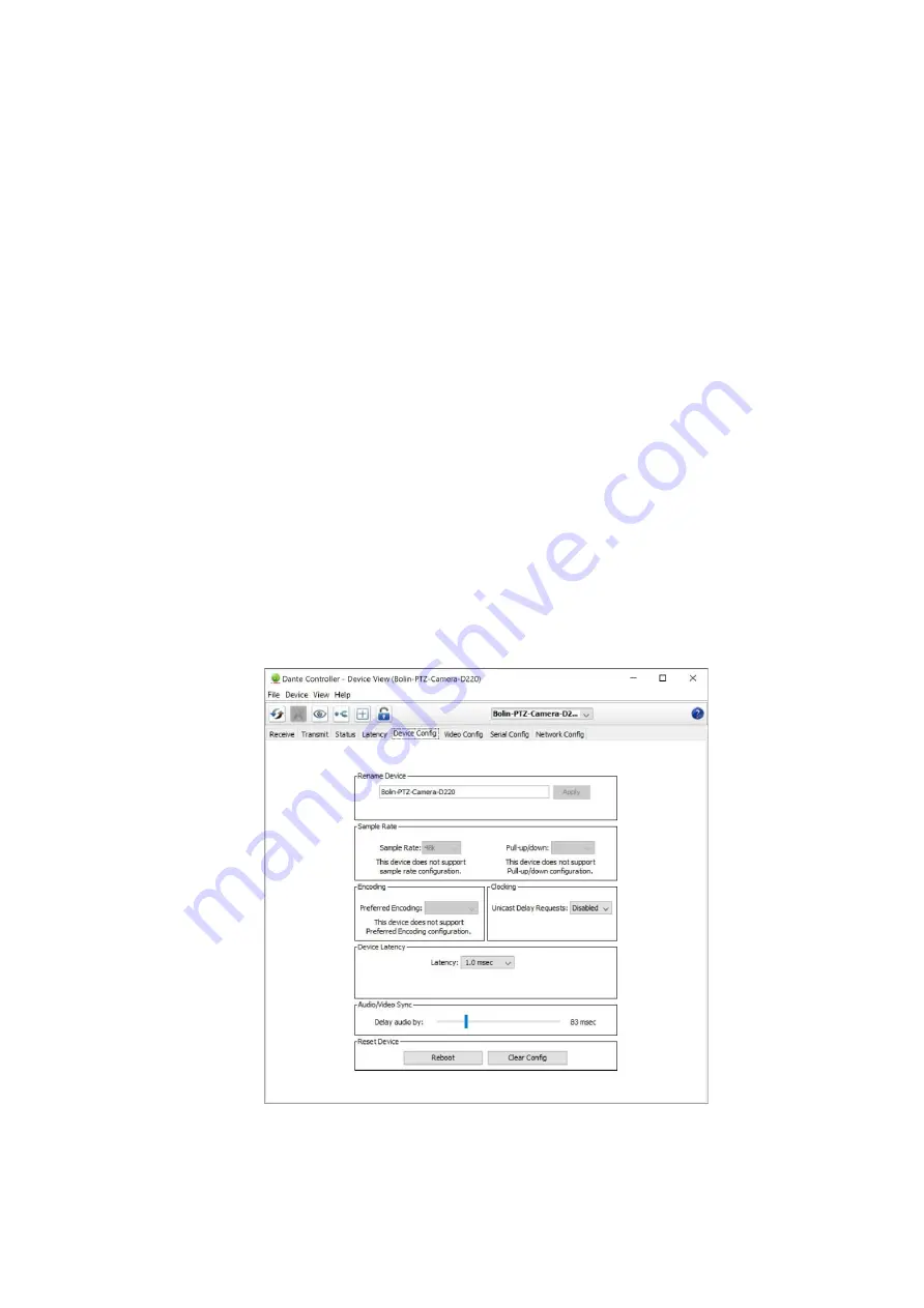
Device Config Tab
This tab on the device view window allows you to configure device specific parameters.
Device Config Tab with Bolin Dante AV camera


