background image

45 


Support Contact Info 

Your experience is important to us. If you need assistance, our support team can be reached by any of the methods 
below: 


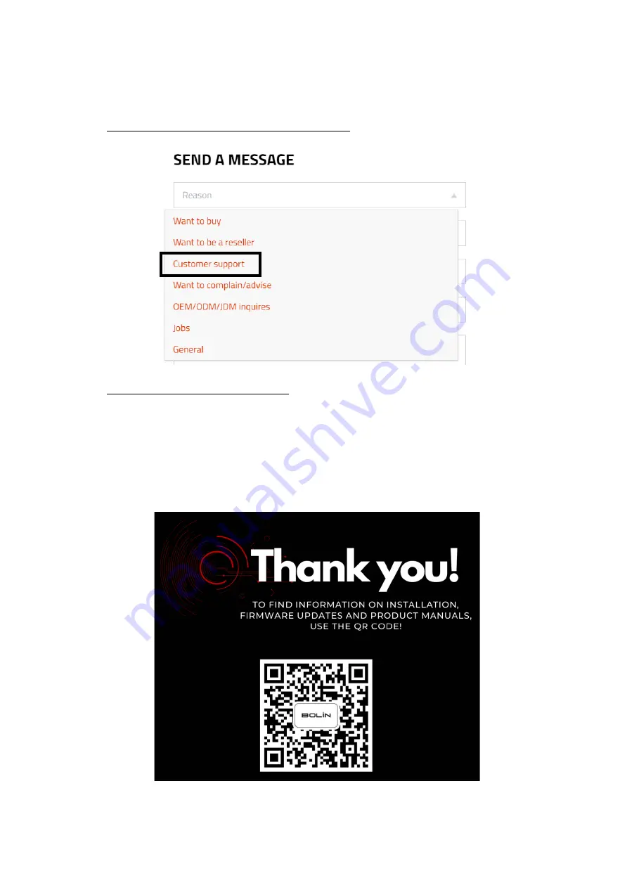
Go to https://bolintechnology.com/company/#contact-us  and select customer support  


Go to https://bolintechnology.com/support/ and use the Raise a Support Ticket button 


Email: [email protected] 


Phone: (626)3336288 ext.104 

Or use your cell phone and mobile device to scan the QR code bellow to have product datasheet and user guide, 
and contact information:  


Summary of Contents for D Series

Page 1: ...1 D Series DANTE AV PTZ Camera USER MANUAL Part One Camera Use VERSION D 09232021 DANTE AV CAMERA D220 2021 Bolin Technology ...

Page 2: ...A 18 RS422 VISCA CONNECTION 18 PELCO P D KEYBOARD RS485 CONNECTION 20 VISCA OVER IP CONTROL 22 TALLY LIGHT GPI I O CONNECTION 23 DIP SWITCH SETTINGS 25 ADJUSTING AND SETTING WITH MENUS 27 EXPOSURE MENU 28 WHITE BALANCE MENU 29 PICTURE MENU 29 PAN TILT ZOOM MENU 30 SYSTEMMENU 31 STATUS MENU 33 FIRMWARE UPGRADE 34 UPGRADING MCU FIRMWARE 34 UPGRADING DANTE AV FIRMWARE 34 OPERATION USING THE INFRARED ...

Page 3: ...3 MENU CONFIGURATION 41 TROUBLESHOOTING 43 WARRANTY 44 SUPPORT CONTACT INFO 45 DIMENSIONS 46 ...

Page 4: ...nterface are the trademarks or registered trademarks of HDMI Licensing LLC in the United States and other countries The Software may contain h 264 AVC video technology the use of which requires the following notice from MPEG LA L L C THIS SOFTWARE IS LICENSED UNDER THE AVC PATENT PORTFOLIO LICENSE FOR THE PERSONAL AND NON COMMERCIAL USE OF A CONSUMER TO I ENCODE VIDEO IN COMPLIANCE WITH THE AVC ST...

Page 5: ...vary with models Please see the actual product for details Due to uncertainties such as physical environment discrepancy may exist between the actual values and reference values provided in this manual Use of this document and the subsequent results shall be entirely on the user s own responsibility Symbols Symbol Description WARNING Contains important safety instructions and indicates situations ...

Page 6: ...erence when the equipment is operated in a commercial environment This equipment generates uses and can radiate radio frequency energy and if not installed and used in accordance with the instruction manual may cause harmful interference to radio communications Operation of this equipment in a residential area is likely to cause harmful interference in which case the user will be required to corre...

Page 7: ...7 WHAT S IN THE BOX Accessories Optional ...

Page 8: ...0P Dante AV 1080P simultaneously Codec with Ultra low Latency mode Synchronized Video and Audio Dante Ecosystem Friendly Instant Dante Ecosystem compatibility with existing Dante enabled products Unified control of audio and video using Dante tools Dante Controller 175 degrees continuous pan 90 degrees to 30 degrees continuous tilt 128 presets Speed up to 150 S Standard mounting and ceiling mounti...

Page 9: ...t supported mic stereo mic plug in power supply voltage 2 5V 0 5V During LINE input input level approx 10 dB 3 dB 7 USB2 0 Firmware upgrade only 8 RJ45 port for RS232 control port 9 RJ45 port for RS 422 485 control port 10 LAN POE IEEE802 3bt for Dante video output 11 HDMI 2 0 4K video output 12 HDMI Cable Secure Mount 13 Power Indicator 14 Lens with 12X optical zoom 15 Tally lamps 16 Status Indic...

Page 10: ...e adjustments Freeze To get a frozen image B Light Back Light compensation OPW One Push White Balance 12 Video Format Switching Works with pressing and holding Fn button 15 You can change the video format by keep pressing the button When video format is changed the camera would restart and the screen turns black for few seconds 13 AI Mode key Set for fan speed adjustment Press AI button once the b...

Page 11: ...ves In locations where the device will be exposed to strong magnetic fields For other potentially questionable locations email Bolin Support for any questions or concerns Safety Matters For your safety please disconnect all power to the device when installing and removing the device Always use supplied accessories and do not modify the s upplied power adaptor Only qualified personnel should instal...

Page 12: ...o use Ceiling Mount bracket and M4 6PW M3 6PW screws for this installation Ceiling mount is sold separately Please following the below diagrams for ceiling mount installation Required accessories and components Ceiling mount installation ...

Page 13: ...ount bracket and M4 6PW screws for this installation Wall mount is sold separately Please following the below diagrams for wall mount installation Required accessories and components Wall mount pendant installation Wall mount standard installation ...

Page 14: ...JEITA type4 supplied with the unit Do not use any other DC power adaptor If using POE to power the camera POE IEEE802 3bt is supported Ensure that the POE power source has sufficient power budget to power the camera or some features may not function properly Cable Requirements For optimal experience with Dante AV it is recommended that the following cables are used for the application HDMI 2 0 or ...

Page 15: ...l be displayed on the HDMI monitor via the Dante AV decoder Audio IN The camera is equipped with a 3 5mm audio input interface supports Line in or Mic audio signal input On rear panel a microphone or audio source can be connected to the MIC LINE Input port which feeds audio into the camera User can select the audio input type to be LINE or MIC via the HDMI OSD menu to adapt the input audio signal ...

Page 16: ... controller or PC control station to operate the camera To perform pan tilt and zoom operations use the joystick of the keyboard controller Preset operation can be done using the control buttons on the keyboard as well An application software that supports this camera is needed if using a PC station RS232 Connection 1 Set RS232 control method on rear panel Dip Switch 2 Set Baud Rate on Bottom Dip ...

Page 17: ...control device 10 Use the included RJ45 to RS422 232 Phoenix terminal contact adaptor to make RS232 connection for your control device 11 Or you can use CAT5 6 network cable T 568B standard pinout to make RS232 connection by following the pin definition below 12 How to make RS232 Daisy Chain multiple camera connection with standard RS232 serial port controller as below ...

Page 18: ...eyboard you are using 3 Set specific camera address that you want to control the camera for via the Bottom Dip Switch 4 If you want to have the camera address automatically assigned by VISCA controller set camera Dip Switch address to 0 5 Reboot the camera after the Bottom Dip Switch has been set up correctly 6 Use the RJ45 to RS422 control cable The controller must be VISCA compatible 7 Camera su...

Page 19: ... RJ45 to RS422 Phoenix connecter adaptor to make RS422 connection for your control device 12 Or you can use CAT5 6 T 568B Standard Ethernet cable direct connect between the camera and the controller to make RS422 connection by following the pin definition below ...

Page 20: ...h Set Baud Rate on Bottom Dip Switch to the same as Baud Rate setting on the keyboard Set the camera ID on OSD menu by remote controller Reboot the camera after the Bottom Dip Switch has been set up correctly Use PELCO P D compatible keyboard Use preset 95 on the keyboard to bring up exit camera OSD menu Use joystick and Button OPEN or CLOSE to navigate OSD menu To operate keyboard please refer to...

Page 21: ... for your control device Or you can use CAT5 6 T 568B Standard Ethernet cable direct connect between the camera and the controller to make RS485 connection by following the pin definition below How to make RS485 multiple cameras connection with RS485 standard serial port controller ...

Page 22: ...s while you are using the RS422 485 connection Operating Multiple Cameras Using RS 232 422 485 Using RS 232 VISCA you can connect to 7 cameras Using RS 422 VISCA you can connect to 7 cameras Using RS 485 PELCO you can connect to 255 cameras Using RS 485 PELCO all camera addresses must be set up before the connection You can set the camera address by operating OSD menu or by setting the Dip Switch ...

Page 23: ...ction between the Keyboard Controller and Video Switcher Sony Set UP 1 GPI I O Input mode Tally signal is sent by Video Switch a Connect camera with keyboard by standard RS 422 control cable b Connect keyboard with video switch by tally function cable c Access to KEYBOARD SETTING GPI I O Setting and change it to Input mode then Exit to home directory d Once the above is done we can switch to diffe...

Page 24: ...the above is done we can switch to different camera by keyboard For example if we switch to camera 1 on keyboard it will send tally signal to camera 1 via standard RS 422 control cable so camera 1 tally light will turn on The keyboard can control camera 1 s pan and zoom at this time d If switch to camera 2 on keyboard then camera 2 tally light will on and camera 1 tally light will go off GPI conne...

Page 25: ...to have the new Dip Switch setting activated Camera ID address and Baud rate setting can be set in camera s OSD menu as well The camera accepts both the changes of OSD menu setting or changes of the DIP switch setting They override each other After the camera is turned on the camera takes the last setting before it is turned on either through the OSD or rear panel DIP switch The DIP Switch Setting...

Page 26: ...ote Controller For example when the camera IR ID is selected 1 on the remote controller press the Camera IR ID button 1 the camera will be controlled by the remote controller When the camera IR ID is selected 3 on the remote controller press the Camera IR ID button 3 the camera will be controlled by remote controller Always check the IR ID on both camera and remote sides and see if they match when...

Page 27: ...nu The name of the setting menu currently selected is displayed here 2 Selected Item Selects a setting item The selected item is shown by the arrow cursor Move the cursor up or down by pressing the button on the infrared remote controller 3 Setting Items The setting items for this setting menu are displayed Select the setting item using the button on the infrared remote controller 4 Set Value The ...

Page 28: ...dB 4dB 6dB 8dB 10dB 12dB 4dB 16dB 18dB 20dB 22dB 24dB 26dB 28dB 30dB IRIS Select the iris from the following F14 F11 F9 6 F8 0 F6 8 F5 6 F4 8 F4 0 F3 4 F2 8 F2 4 F2 0 F1 8 CLOSE SPEED Select the speed from the following when video resolution set to NTSC format 1 30 1 60 1 90 1 100 1 125 1 180 1 250 1 350 1 500 1 725 1 1000 1 1500 1 2000 1 3000 1 4000 1 6000 1 10K Select the speed from the followin...

Page 29: ...ne according to the temperature of the light source illuminating the subject USER This is a mode that enables you to manually set the control of R and B gain up to 256 steps NOTE When you select USER R GAIN red gain and B GAIN blue gain appear You can select each item in the range from 0 to 255 PICTURE Menu SHARPNESS Picture sharpness value ranges from 0 to 15 You can enjoy emphasized edge and hig...

Page 30: ...is available the resolution decreases ZOOM RATIO OSD Zoom times display Set Ratio OSD to ON the number of the zoom ratio that you are operating displays on screen VIDEO PARAMETERS Set Video Parameters OSD to ON the value of the setting and parameter will be displayed on screen when you use remote controller to adjust the camera image parameters using the direct adjust buttons or with the feature k...

Page 31: ...g the joystick controller pan tilt zoom operations can t be performed simultaneously Call preset 1 to finish and stop the trace recording NOTE The recording automatically stops after the maximum recording time has elapsed Playing Trace Memory pan tilt zoom operations Select the recorded trace number you want to play in TRACE NO Move the cursor to MEMORY select PLAY and press HOME button or Joystic...

Page 32: ...icrophone and capture the Mic audio source VOLUME LEVEL To adjust the audio gain value o LINE audio gain value can be adjusted from the following 34 5dB to 33dB o MIC audio gain value can be adjusted from the following 6dB 9dB 12dB 15dB 20dB 40dB PLUGIN POWER Available when Input Type is set to MIC o OFF Disable plugin power for the connected microphone In this case the microphone needs to be powe...

Page 33: ...ly get the active status of the camera s settings NOTE You can adjust the camera fan speed through the status menu FAN LEVEL 3 levels are supported LOW MID and HIGH The higher the level the faster the fan speed EXPOSURE WHITE BALANCE PICTURE PAN TILT ZOOM SYSTEM STATUS OSD NEXT PAGE PELCO ID 1 IR ID 1 BAUD RATE 9600 COMM TYPE 422 FORMAT 1080p60 SV VOC260B37040AA006 SYSTEM MENU EXPOSURE WHITE BALAN...

Page 34: ...flash drive Formatted as FAT32 and rename the file as HD20 bin 2 With the camera powered off insert the flash drive to the USB port on the back panel of the camera 3 Apply power to the camera The green Status indicator light on the front panel of the camera will turn red for a few seconds while the upgrade takes place Once the upgrade is finished the light will turn back to green The camera will p...

Page 35: ...from the camera is rotated toward the right whenever you press the button To face the camera toward the opposite direction You might wish to face the camera towards the opposite direction from that of the button you pressed for example when you change the direction of the camera while checking the picture on the screen In such a case press and hold the Fn key then press the 2 REV button Arrow butt...

Page 36: ...ys firstly check if the IR ID is set correctly same as the IR ID set on the camera when the camera is not responding to the IR controller Then you can operate the camera s specified by number Every time you operate the camera s using the IR remote controller the Camera IR ID button pressed in step 2 fleshes Adjusting the Camera Focus Focusing on a Subject Focusing the camera on a subject automatic...

Page 37: ...ESET button to delete reset the pan tilt position 2 Adjust the position zooming focus and backlighting of the camera While holding down the PRESET button press any of the POSITION buttons 1 to 9 in which you want to store the settings Recalling the stored settings Press any of the POSITION buttons 1 to 9 in which you have stored the settings Cancelling the preset memory While holding down the RESE...

Page 38: ...rea the PT S button light will off Zoom S Adjust Zoom Speed Press Zoom S button Zoom S button light will on then press or button to adjust zoom speed value After done press other button in this area the Zoom S button light will off Preset S Adjust Preset Speed Press Preset S button Preset S button light will on then press or button to adjust preset speed value After done press other button in this...

Page 39: ... that the camera can pan to Use the arrow keys to turn the camera to the leftmost position you want to set press and hold the Fn key then press and hold 5 Left Limit button for 1 second The left limit position has now been set When the camera is turning to the left and reaches the left limit position the camera will stop Press and hold Fn key then press and hold 5 Left Limit for 3 seconds the left...

Page 40: ... Resolutions Press and hold Fn button then press the Resolution button to populate a menu where you can switch resolutions Use the arrow keys to navigate Press Home to select Screen will show CHANGING Press Menu to exit ...

Page 41: ...41 Menu Configuration The menus of camera are configured as described below OSD Menu Configuration ...

Page 42: ...42 ...

Page 43: ...he front of the device Please verify that it is on the ON position Use the supplied power adaptor or a proper rating PoE device Ensure wirings are properly connected and plugs are securely in place If the decoder is attached to an outlet with a power switch please make sure the switch is on Decoder will restart by itself The decoder may not be getting sufficient power Verify on our website at www ...

Page 44: ...luding without limitation direct or indirect arising out of or relating to Bolin products Inconvenience or any loss arising when images are not displayed due to any reason or cause including any failure or problem with the Bolin products Loss of registered information or data caused by any failure Any compensation claims demands etc resulting from infringement of privacy by individuals or organiza...

Page 45: ... https bolintechnology com company contact us and select customer support Go to https bolintechnology com support and use the Raise a Support Ticket button Email support bolintechnology com Phone 626 3336288 ext 104 Or use your cell phone and mobile device to scan the QR code bellow to have product datasheet and user guide and contact information ...

Page 46: ...46 Dimensions Unit mm ...

Page 47: ...47 www bolintechnology com 2082 TECHNOLOGY LLC dba BOLIN TECHNOLOGY ...

Reviews: